Continue to Site

Welcome to EDAboard.com

Welcome to our site! EDAboard.com is an international Electronics Discussion Forum focused on EDA software, circuits, schematics, books, theory, papers, asic, pld, 8051, DSP, Network, RF, Analog Design, PCB, Service Manuals... and a whole lot more! To participate you need to register. Registration is free. Click here to register now.

LC tank of VCO quality factor vs frequency plot

Status
Not open for further replies.
R

rty94

Guest
Hello,

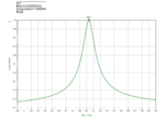
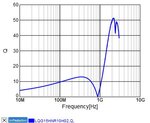
Which is the right way to plot quality factor versus frequency of the tank? Could someone describe it?

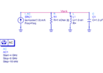
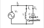
Should I simulate standalone the LC tank with a port connected to the two pins p1 and p2 of my tank via an ideal balun or should I simulate it with the whole VCO topology for receiving the right results?

Also should I define specific param for the port ?
 

You can simulate directly RLC Circuit by simple AC analysis in order to find "Unloaded[*] Q Factor"
But this one will be a bit erroneous because Active Part of the VCO will definitely load the Tank Circuit.
Plot Impedance vs Frequency Curve of the Tank Circuit and find the R Value at Peak Resonance Frequency then calculate Q as
\[ Q_{u}=R\sqrt{\frac{C}{L}} \]
 

Thanks! For AC analysis I will put an AC magnitude(eg 1mV) to the Vctrl source and then VF(net)/IF(current) for finding impedance?
 

Us this sample.You will know L,C and R then you can find Q.
 

Attachments

  • resonator1.png
    resonator1.png
    192.5 KB · Views: 243
  • resonator2.png
    resonator2.png
    101.8 KB · Views: 237

    R

    Points: 2
    Helpful Answer Positive Rating
For better accuracy, the Q-factor of an LCR circuit should contain the Q-factor model of the L and C components.
For low frequencies this would not be very important, but for higher frequencies and especially for inductors, their Q-factor could make a big difference in getting the right LCR Q-factor.
For example see the attached Q-factor of a Murata SMD size 1005, 100nH inductor vs frequency.

The data was taken from here:
 

Attachments

  • 100nH_SMD1005.jpg
    100nH_SMD1005.jpg
    23.5 KB · Views: 193

When I add an equivalent parasitic C from active devices, the Rp of the tank will get higher so the quality factor too. Is this a right setup for loaded Q? Should I use an ideal cap from analog lib for parasitics as to not change Rp?
 

Attachments

  • Tank.jpeg
    Tank.jpeg
    34 KB · Views: 162

Status
Not open for further replies.

Part and Inventory Search

Welcome to EDABoard.com

Sponsor

Back
Top