Dale Gregg
Junior Member level 3
- Joined
- Jul 23, 2013
- Messages
- 29
- Helped
- 2
- Reputation
- 4
- Reaction score
- 2
- Trophy points
- 3
- Location
- Leeds, United Kingdom
- Activity points
- 263
Hi,
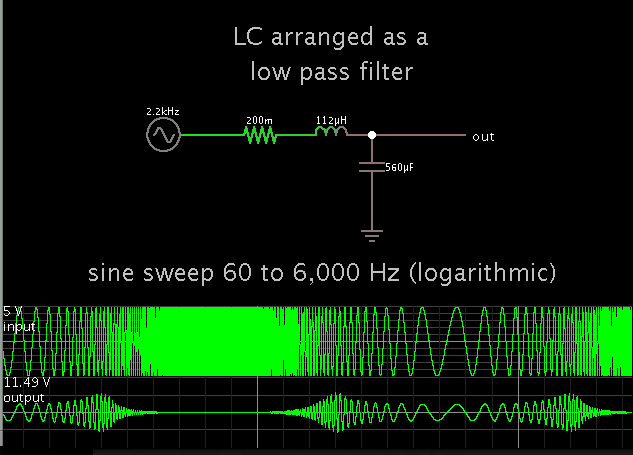
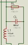
I designing a H-bridge inverter using a SPWM signal. I'm now trying to calculate the LC low pass filter circuit values. I understand the cut off frequency equation (Fc=1/(2*pi()*sqrt(LC))) but I don't want to just trial and error the values, or is this the normal way? I tried using the inductor voltage eq. V=L(di/dt) transposed as L=V(dt/di) but then realised I dont know what the Vdrop is.
Its probably a stupid question (I'm good at those ) but some advice on how this is normally done would be great as I've been stuck for while.
Dale
I designing a H-bridge inverter using a SPWM signal. I'm now trying to calculate the LC low pass filter circuit values. I understand the cut off frequency equation (Fc=1/(2*pi()*sqrt(LC))) but I don't want to just trial and error the values, or is this the normal way? I tried using the inductor voltage eq. V=L(di/dt) transposed as L=V(dt/di) but then realised I dont know what the Vdrop is.
Its probably a stupid question (I'm good at those
) but some advice on how this is normally done would be great as I've been stuck for while.Dale