Continue to Site

Welcome to EDAboard.com

Welcome to our site! EDAboard.com is an international Electronics Discussion Forum focused on EDA software, circuits, schematics, books, theory, papers, asic, pld, 8051, DSP, Network, RF, Analog Design, PCB, Service Manuals... and a whole lot more! To participate you need to register. Registration is free. Click here to register now.

Lattice iCE40-HX8K Board - UART

Status
Not open for further replies.

Zumbi

Newbie level 4
Joined
Sep 4, 2015
Messages
5
Helped
0
Reputation
0
Reaction score
0
Trophy points
1
Activity points
48
Hello,

I have the following verilog code for my Lattice iCE40-HX8K Board:

uart.v:

Code:
module uart(input clk, output TXD);

reg [3:0] count;
reg [9:0] data;
reg z;

initial begin

data[9:0] = 10'b1000000000; // Startbit = 1, Stopbit = 0

z = 0;

end

always@(posedge clk)
begin

  if(count == 1250) //9600x per Second (1250) = Baudrate
    begin

      count <= 0;

      TXD = data[z];

      z = z + 1;

      if(z == 10)
        begin
        z = 0;
        end
      else
        begin
        end

    end
  else
    begin
      count <= count + 1;
    end


end

endmodule


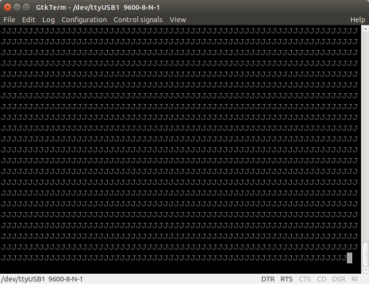
For receiving the UART-Data I use gtkterm under Ubuntu 14.04.
I have set the baudrate in gtkterm to 9600.
If I now program my FPGA with the code I receive once per programming a
hex "00" (irrespective of the 8 usage-bits).

Screenshot from 2015-09-04 21:17:26.png

Can anybody give me a hint what is wrong?

Thank you for your support.
Sincerely,
Zumbi
 

If you have an oscilloscope available - watch the signals
 

is this your board?
https://www.latticesemi.com/en/Products/DevelopmentBoardsAndKits/iCE40HX8KBreakoutBoard.aspx

Where do you have your UART conected to your PC ... at the USB or at GPIO?

I guest the USB are used to program the FPGA,so maybe you could run your UART on a GPIO pin.

I can recommend to use the FTDI USB/rs232 TTL 5v or 3v3 lever to work with such projects
https://www.ftdichip.com/Products/Cables/USBTTLSerial.htm

Also try to make a loop-back on your tx/rx from the PC side and see you can echo what you send from the PC side and it stops when you break the loop-back ... then you know for sure you terminal program does work.
 

I've know fixed two problems:

1. count has to be at least 11 Bits wide to count to 1250
2. z has to be at least 4 Bits wide to count to 10
3. Removed non-blocking assignments (<=)

The code know looks like this:

Code:
module uart(input clk, output TXD);

reg [10:0] count;
reg [9:0] data;
reg [3:0] z;

initial begin

data[9:0] = 10'b0010100101; // Startbit = 0, Stopbit = 1

z = 0;

end


always@(posedge clk)
begin

  if(count == 1250) //9600x pro Sekunde (1250) = Baudrate
    begin

      count = 0;
      TXD = data[z];
      z = z + 1;

      if(z == 10)
        begin
        z = 0;
        end
      else
        begin
        end

    end
  else
    begin
      count = count + 1;
    end


end

endmodule

I am now receiving an endless chain of "J":


But if I take a look at the data bits inside "data":

01010010

I should receive a ASCII "R".
My question is now why I am getting a "J" instead of an "R"?
Can anybody give me a hint what might be wrong?
Thank you a lot :)

is this your board?
**broken link removed**

Yes it is.

Where do you have your UART conected to your PC ... at the USB or at GPIO?

I've connected the board via USB to my PC.


Also try to make a loop-back on your tx/rx from the PC side and see you can echo what you send from the PC side and it stops when you break the loop-back ... then you know for sure you terminal program does work.

I've already tried this and it works perfectly.

Sincerely,
Zumby
 

If you look up ACSII for "R" it's 0x52 = 0101 0010 and for "J" it's "0x4A" = 0100 1010
It's the same but rotated the other direction :)

You need to send LSB first

https://en.wikipedia.org/wiki/RS-232


If you look up ACSII for "R" it's 0x52 = 0101 0010 and for "J" it's "0x4A" = 0100 1010
It's the same but rotated the other direction :)

You need to send LSB first

https://en.wikipedia.org/wiki/RS-232


Thank you for your fast response :)
If I rotate only the data bits the result is still sometimes wrong:

Code:
data[9:0] = 10'b0111111111; --> Result: FF (HEX) --> Correct
data[9:0] = 10'b0100111001; --> Result: 9 (ASCII) = 39 (HEX) --> Correct
BUT:

Code:
data[9:0] = 10'b0100011001 --> Result: 19 (HEX) (ASCII not readable character, but should be 1) --> WRONG, should be 31 (HEX)
Does anybody why it is sometimes wrong and sometimes it isn't?
I've tested it with three different programs in total but always the same wrong results.
As always, thank you for your support :)

Sincerely,
Zumbi
 
Last edited by a moderator:

Think your terminal program are confused when you rotate the other way and have not fixed the start / stop bit
You need to keep your start bit as 0 and your stopbit as 1 even when you rotate the other way

in your original code you had
Code:
data[9:0] = 10'b0010100101; // Startbit = 0, Stopbit = 1

try
Code:
data[9:0] = 10'b1010100100; //  Stopbit = 1, Startbit = 0
 
Last edited by a moderator:

I've also tried to switch the start- und stop bits, but the result remains wrong.
Any other ideas?

Sincerely,
Zumbi
 

What is the frequency of your clock?
Try to have gtkterm to show HEX
Try to make some test and send

0x01, 0x02, 0x04, 0x08, 0x10, 0x20, 0x80 this will use just 1 bit high at a time

also good char to send are 0x55 and oxAA since you wil have pattern 01010101 and 10101010

if you se someting different on your term program your bitrat emight be wrong 9600 shall have a time of 104uS per bit

I know from a rotating led example that 1s from clock equals 12000000 cycles (posedge clk).
So if I calculate 12000000 / 9600 (Baudrate) = 1250 (value in if-statement counter)
I've also set the Baudrate in gtkterm to 9600.
So I'm not thinking that this might be the issue, isn't it?

But I've made a new realization:
If I unplug the board from the usb and plug it back in (and restart gtkterm) the result that I see in gtkterm changes.
At specific hex values for the data-bits I get first (without unplugging and restarting gtkterm) a wrong result and then after unplugging and restarting I get the right result.
How can this be explained?

Sincerely,
Zumbi
 

I did look in the doc for your board. yes the freq are 12Mhz and a div of 1250 will be good.
The USB does got the the FT2232 end this chip do ahe the tx/rz as well as SPI interface to probely program the FPGA. It could be the combination of both programming and RX/TX which give you the problem.

But it could also be the you have no pause between the bytes you send ... so the terminal software might lock to wrong stop/start bit.

You can try to add in a extra "stopbit" so there are a little delay between bytes send.

Please also have a look here, great site

https://www.fpga4fun.com/SerialInterface.html
 

I've know fixed two problems:

1. count has to be at least 11 Bits wide to count to 1250
2. z has to be at least 4 Bits wide to count to 10
3. Removed non-blocking assignments (<=)

The code know looks like this:

Code:
always@(posedge clk)
begin

  if(count == 1250) //9600x pro Sekunde (1250) = Baudrate
    begin

      count = 0;
      TXD = data[z];
      z = z + 1;

      if(z == 10)
        begin
        z = 0;
        end
      else
        begin
        end

    end
  else
    begin
      count = count + 1;
    end


end

Wrong, removing non-blocking assignments could easily result in synthesis simulation mismatches as you are reading the value of z in multiple locations in the code, which has a blocking assignment for z.

Flip-flops are represented in Verilog with non-blocking assignments. Combinational logic is represented by blocking assignments. And it's good practice to never mix the two.
 

Status
Not open for further replies.

Part and Inventory Search

Welcome to EDABoard.com

Sponsor

Back
Top