Continue to Site

Welcome to EDAboard.com

Welcome to our site! EDAboard.com is an international Electronics Discussion Forum focused on EDA software, circuits, schematics, books, theory, papers, asic, pld, 8051, DSP, Network, RF, Analog Design, PCB, Service Manuals... and a whole lot more! To participate you need to register. Registration is free. Click here to register now.

Laser Instant Switch ( sensor )

Status
Not open for further replies.

goldperson2005

Junior Member level 2
Joined
Nov 8, 2011
Messages
21
Helped
1
Reputation
2
Reaction score
1
Trophy points
1,283
Activity points
1,420
Hi guys
I need Laser Instant Switch for my project . I've searched about it trough the web , but the laser switching time were about ms(fall and rise time ) , and in phototransistors it was about us .
In my project rise/fall time shouldn't be more than 499ps .
I want to use laser to measure the time between two events . The time that I try to measure is about 3.5ns to 1ms ( the resolution should be at least 0.5ns ) .
The response time (both Rise/Fall) of the laser instant switch should be at least 499ps ( ; 499ps after receiving the spectrums of laser it should trigger starting time measurement ) .
Please let me know how should I figure it out ?

- - - Updated - - -----------------------------------------------------------------------------------------------------------------------------------------------------------------

Can any one present LaserDiodes in ps response time ( both Rise/Fall ) ?
 

Why don't you provide more details about your setup - then maybe someone can suggest an alternate method of how to achieve your end objective.
 

Thanks
What kind of detail should I provide ?
I want to use LaserDiode to trigger the start and stop of time measurement .
 

It is not clear what you are trying to do. Using a laser to measure the time between two events implies breaking the beam but you talk about switching the laser with a rise time of less that 499ps - a very precise figure. Are you making a time of flight rangefinder? How are you planning to time things - your timing requirement implies a clock of at least 2GHz unless you are using a TDC chip?

Also, a laser is only a light source - what is the detector?

Keith
 
thanks
as you said , " Using a laser to measure the time between two events implies breaking the beam " ; Start by breaking the beam & stop by receiving it again .
it's repetitive & should be accurate at least in 0.5ns . If the response time be more than 499ps it may lose . Yes I want to use TDC chip .
I want to use optical fiber and LeaserDiode as detector .
 

I want to use optical fiber and LeaserDiode as detector .

A laser diode isn't a detector. I would suggest you look at a fast PIN photodiode for the detector. Assuming you have lots of signal you should be able to use a simple resistive load (50 ohms or less) for the photodiode. However, you will not find it easy to get <499ps rise time. You need to be looking at 0.2mm diameter PIN photodiodes and similarly high speed (1GHz) circuitry. TDCs don't usually require such fast rise/fall times. Acam resolves down to 22ps and specifies a maximum of 200ns rise time although I think for repeatable results I would like a faster rise time than that!

Keith
 
Thanks Keith
TDC 2.jpg
They defined just the max range of rise/fall time . I haven't read the whole of the datasheet , but I think it's trying to say that the maximum rise/fall time of input shouldn't be over than 200ns .
but the other point that I can not figure it out :
TDC 1.png
according to the image , it won't measure whole the time .
what is your idea ? does it measure whole the time ?
Is the time measured by TDC different from the time measured with High-Speed Unit of TDC ?
 

As far as I understand it in mode 2 you still get the whole time but it measures it with a coarse time and fine time in order to extend the measuring time to 4ms whereas mode 1 will only measure to 2.5us. Mode 2 would normally be used for "slower" measurements such as ultrasound whereas mode 1 would be for optical measurements. I assume you are looking at something like the TDC-GP22.

Keith.
 
Yes , I'm looking at TDC-GP22 .
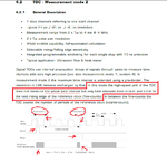
I can not understand this :
" In mode 2 the high-speed unit of the TDC does not measure the whole time interval but only time intervals from START and STOP to the next rising edge of the reference clock (fine-counts) "
according to this part it shouldn't measure whole the time ?
Please let me know how can I be sure that in mode 2 , it measures whole the time ?
 

Yes, it measures the whole time. You must also read the sentence that follows: "In between the fine-counts the TDC counts the number of periods of the reference clock (coarse-count)." So, it adds the two together to get the total time (allowing for the difference in resolution between the two counts).

Keith
 
Then accuracy strongly should depends on frequency stability ( ; vs all features ) .
 

Status
Not open for further replies.

Part and Inventory Search

Welcome to EDABoard.com

Sponsor

Back
Top