Continue to Site

Welcome to EDAboard.com

Welcome to our site! EDAboard.com is an international Electronics Discussion Forum focused on EDA software, circuits, schematics, books, theory, papers, asic, pld, 8051, DSP, Network, RF, Analog Design, PCB, Service Manuals... and a whole lot more! To participate you need to register. Registration is free. Click here to register now.

Laser diode

Status
Not open for further replies.

tnnedaboard

Member level 3
Joined
Apr 5, 2012
Messages
64
Helped
0
Reputation
0
Reaction score
0
Trophy points
1,286
Activity points
1,748
Hi,
I wanted some help kindly

can i use the same digital potentiometer for 9 laser diode?

obviously I will have a single setting for all 9...

TEST.jpg
 

Should be OK, the input bias current of the LM324 is quite low, the potentiometer should be able to supply it easily.

R4/R5 seem low in value, they could probably be scaled up significantly.

Brian.
 

Short answer is yes.

But your control range suffers because of LM324 limited output range. Consider a RRIO
part. The LM324 has severely limited Input and output range.


The input range, you are violating its CM input range.


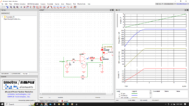
1676908174858.png


Also the Pdiss of Q1 a tad high for a TO92, if you correct problems and operate 500 mA or
more, maybe put a heatsink on it or use a TO92+type package.

Note I used an ordinary diode for sim, not knowing what your Laser part number is. 3 Diodes
used to sim a red laser diode Vthreshold.


Regards, Dana.
 

Attachments

  • 1676906007313.png
    1676906007313.png
    120.5 KB · Views: 86
Last edited:

Hi,

I agree with the posts above.

* usually you want low voltage drop at R6 (to increase regulation range), thus reduce the value, maybe to 1V.
(in detail it depends on your expected Laser current range)
* R4 is counter-productive, it makes it impossible to get a clean current regulation. Disconnect it.
* R5 should be 1k ... maybe up to 10k.
* C3 depends on expected regulation speed. I´d say 1nF or higher, maybe up to several uF.
(It forms a low pass filter with R5. .. and ensures OPAMP output not to oscillate)

I don´t understand the potentiometer connetions at all.
* Missing signals.
* What do you want to achieve?

Klaus
 

Note I used an ordinary diode for sim, not knowing what yoru Laser part number is.
I recovered the diode lasers from an old application, I don't know exactly the mWatt sure below 100...
near the case I can read L96 4G5P, but I can't find the related datasheet...???

1676908749388.png
 

There is one common pin, one to the laser diode and one to the light monitor. If you want better control of the emitted light, use the monitor pin as the feedback signal. These diodes can run hot and their characteristics change with temperature, monitoring the light output instead of the laser current will give far better control.

The comments about rail to rail op-amps are quite correct but if you want to stay with the LM324, try putting say -5V on pin 11 so the input pin voltages are further away from ground.

Brian.
 

I recovered the diode lasers from an old application, I don't know exactly the mWatt sure below 100...
near the case I can read L96 4G5P, but I can't find the related datasheet...???

View attachment 181362


So you do not know what max current is thru diode and its thermals ?

Good way of roasting a lot of parts. You have to design to parameters.


Regards, Dana
 
Hi Dana
obviously I did some tests with that circuit you see and everything works correctly...
the question was if with the same digital potentiometer I could connect 9...
could you help me, to identify the right datasheet, based on the abbreviation L96 4G5P that is on the laser diode?
--- Updated ---

obviously I did some tests with that circuit you see and everything works correctly...
the question was if with the same digital potentiometer I could connect 9...
could you help me, to identify the right datasheet, based on the abbreviation L96 4G5P that is on the laser diode?

I found these...

Best Regards
Tony
 

Attachments

  • diodo laser_650nm_adl_65103tl_eng.pdf
    541 KB · Views: 84
  • diodo laser_hl65241dg_242dg_243dg.pdf
    241.4 KB · Views: 82
Last edited:

The middle pin seems to always be the common, so use a 10K
R, with a supply of 5V, and measure the circuit V across a leg to
common to establish which diode and its polarity is connected
internal to 1 or 3, the outside pin under test.

1676980836352.png


Regards, Dana
 

The diode test circuit :

1676984988245.jpeg


Forward polarity the diode will measure 1 - 3 V, reverse the V source in the circuit, in this
case 12V.

Regards, Dana.
 

Your measurement looks correct.

Now confirm the other diode is good, pin 1, remove all connections,
put black on 1, red on 2, common, you should see a V then showing that
diode is good.

regards, Dana.
 

Hi,
I did the test, with red on 2 and black on 1... but I don't have any measurements....?
yet when I disassembled the laser diode it worked...:unsure:
 

Status
Not open for further replies.

Similar threads

Part and Inventory Search

Welcome to EDABoard.com

Sponsor

Back
Top