Continue to Site

Welcome to EDAboard.com

Welcome to our site! EDAboard.com is an international Electronics Discussion Forum focused on EDA software, circuits, schematics, books, theory, papers, asic, pld, 8051, DSP, Network, RF, Analog Design, PCB, Service Manuals... and a whole lot more! To participate you need to register. Registration is free. Click here to register now.

Laser diode and photodiode circuit

Status
Not open for further replies.

GeoAVR

Member level 2
Joined
Jun 4, 2014
Messages
48
Helped
0
Reputation
0
Reaction score
0
Trophy points
6
Activity points
366
Hi all,

I want to control the Bias and Modulation current of a laser diode using a microcontroller, a DAC and discrete components (including operational amplifiers).
Current range 3mA to 25mA with 0.1mA step.
Current pulses: rise time few nanoseconds, 10% max overshoot

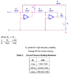
I have found this circuit from TI that controls the current based on its input voltage:
current source.png

1. Will it work?
2. How can I combine two of them for adding Bias and Modulation current?


I need also a current to voltage converter at the photodiode. I need to detect the pulses and their current.
What do u propose?

Thank you
 

You can safely forget about this approach. Don't expect to achieve ns pulses with closed loop feedback current source.

Try something using transistor current sources respectively transistor as V/I converter.

In a 10 ns range, GHz OP based current sources can be an option.
 
  • Like
Reactions: GeoAVR

    GeoAVR

    Points: 2
    Helpful Answer Positive Rating
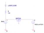
I was thinking something like this for adding the modulation current:

block.png

Will the switch cause spikes in the pulses?
What Voltage controlled current source do you propose?
 

You can't switch a current source by a single-throw switch. This forces the current source into saturation and causes huge recovery times and overshoot.

Instead should think about differential pairs (BJT or MOS) as non-saturated current switches.
 
  • Like
Reactions: GeoAVR

    GeoAVR

    Points: 2
    Helpful Answer Positive Rating
You can't switch a current source by a single-throw switch. This forces the current source into saturation and causes huge recovery times and overshoot.

Instead should think about differential pairs (BJT or MOS) as non-saturated current switches.

Actually I found a driver ic with similar topology:

laser diode driver.png

Any ideas how to implement it with discrete components?
 

A laser diode driven in constant current mode can be implemented with a programmable current source which can be digitally controlled by an DAC. The loop control time depends signal chain - sensing, calculating and output to the DAC). The settling time of the DAC plus programmable current source, as well as the inductivity(wiring etc.) define the rise and fall times(https://www.ichaus.de/wp4_fastlaserdriver ). Fast laser switches, like the iC-HK could be used to switch between two current values. If the laser diode has a monitor diode the control loop can be different.

Enjoy your design work!
 

I was thinking something like this for adding the modulation current:

View attachment 113699

Will the switch cause spikes in the pulses?
What Voltage controlled current source do you propose?

Does some one has simulation model for laser diode?
plz help
 

Hello Gigan,

The above model description does not include the wiring inductance. It is very important to keep is low to achieve fast switching and low overshoots. On modelling laser diodes check-out this paper with Mathlab: **broken link removed** .

Enjoy your design work!
 
  • Like
Reactions: GeoAVR

    GeoAVR

    Points: 2
    Helpful Answer Positive Rating
Status
Not open for further replies.

Similar threads

Part and Inventory Search

Welcome to EDABoard.com

Sponsor

Back
Top