Continue to Site

Welcome to EDAboard.com

Welcome to our site! EDAboard.com is an international Electronics Discussion Forum focused on EDA software, circuits, schematics, books, theory, papers, asic, pld, 8051, DSP, Network, RF, Analog Design, PCB, Service Manuals... and a whole lot more! To participate you need to register. Registration is free. Click here to register now.

[SOLVED] KVL, KCL, Nodal and Mesh Analysis

Status
Not open for further replies.

Hatmpatn

Member level 3
Joined
Sep 15, 2014
Messages
59
Helped
0
Reputation
0
Reaction score
0
Trophy points
6
Activity points
515
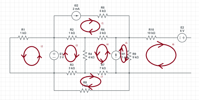
Hey all! I'm new to this forum and very new to the subject of electronics. I'm quite eager to learn more of the theory of electronics and I'm therefore taking a basics course in it.
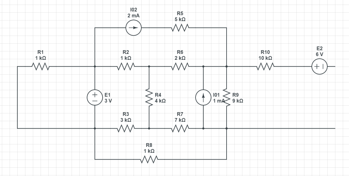
I'm already stuck on this problem and I would love if any of you guys would direct me to the right path to solve this problem. I don't want any complete answer for the problem, only what I should start out with to solve this.


I'm allowed to use Ohms law, Kirchoff's Law of Current, Kirchoff's Law of Voltage, Nodal Analysis, Mesh Analysis or the method with incidence matrices.

What should I begin with, maybe start simplifying the circuit, how?
 
Last edited by a moderator:

OK.. then let us start with Mesh analysis. It is an easy approach although other are easy too but I use this approach frequently. I can help you with it. Let us start. First mark loops in this circuit. There are 7 loops. Can you figure them out?
 
Thanks for the answer Eshal!

Here is where I think the meshes are located:


But is I6 really a mesh, or is the 7th mest you're referring to a "supermest" i the I4/I5 area?
 
Last edited by a moderator:

What is the problem? Are you supposed to find a Thevenin equivalent at the right end of the circuit? Must you find the voltage across every resistor? Find the total power dissipated in the circuit?

It really helps if you specify just what you're required to do.
 
Cant believe I forgot to tell you what the goal is with this problem, sorry!
Yes, I'm supposed to find the Thevenin equivalent to this problem.
 

What method have you learned for finding the Thevenin equivalent? Possibly the method where you find the short circuit current and the open circuit voltage at the output port?

Or, the method where you apply a test voltage at the output port and calculate the current?

This is a fairly complicated circuit, and it's easy to make a mistake when you're setting up 7 equations. How will you solve the equations? Do you use a program like Matlab or Mathcad? Or do you use a calculator?

For such a complicated circuit, I would solve it by two methods such as mesh and nodal analysis, and compare answers. If you're a beginner, that would be good practice anyway.

If you use the mesh method, you will have a supermesh. If you use the nodal method, you will have a supernode.
 
Thanks for the reply The Electrician. I would like to solve it using the two methods such as mesh and nodal analysis and then compare the answers.

vep66c.png

Is this the correct way to go about things? But now there is only 6 meshes, whereas there should be 7 according to Eshal?

Are the directions of the current correct in the meshes?
 
Last edited by a moderator:

I would stick with the original 7 meshes, realizing that I4 and I5 together comprise a supermesh but you won't deal with that at first. Ultimately, you will have one equation for the supermesh and one "constraint" equation showing the relation between I4 and I5.

I find that a good way to proceed, at first, is to write the 7 mesh equations as though I4 and I5 don't form a supermesh. When you have the 7 equations, then I'll show you how to deal with the supermesh.

The current directions are arbitrary. Just let them all be clockwise and it will be ok.
 
Ok, then I have set the original meshes to going clockwise and will now perform the calculations for these.

uppg1slingor.png

Following calculations were made(please see that these are correct).

I1: 5kΩ(I1)+2kΩ(I1-I4)+1kΩ(I1-I3)=0
I1(5kΩ+2kΩ+1kΩ)-I3(1kΩ)-I4(2kΩ)=0
I1(8kΩ)-I3(1kΩ)-I4(2kΩ)=0

I2: -3V+I2(1kΩ)=0
I2(1kΩ)=3V

I3: -3V+1kΩ(I3-I1)+4kΩ(I3-I4)+3kΩ(I3-I7)=0
-I1(1kΩ)+I3(1kΩ+4kΩ+3kΩ)-I4(4kΩ)-I7(3kΩ)=3V
-I1(1kΩ)+I3(8kΩ)-I4(4kΩ)-I7(3kΩ)=3V

I4: 4kΩ(I4-I3)+2kΩ(I4-I1)+7kΩ(I4-I7)=0
-I1(2kΩ)-I3(4kΩ)+I4(4kΩ+2k»+7kΩ)-I7(7kΩ)=0
-I1(2kΩ)-I3(4kΩ)+I4(13kΩ)-I7(7kΩ)=0

I5: 9kΩ(I5-I6)=0
I5(9kΩ)-I6(9kΩ)=0

I6: 9kΩ(I6-I5)+10kΩ(I6)=0
-I5(9kΩ)+I6(9kΩ+10kΩ)=0
-I5(9kΩ)+I6(19kΩ)=0

I7: 3kΩ(I7-I3)+7kΩ(I7-I4)+1kΩ(I7)=0
-I3(3kΩ)-I4(7kΩ)+I7(3kΩ+7kΩ+1kΩ)=0
-I3(3kΩ)-I4(7kΩ)+I7(11kΩ)=0

When I put these values in as a matrix A(becomes a big 7x7 matrix), and then set B to be vector with the voltage values(B=[0; 3; 3; 0; 0; 0; 0;]).

I then get a new vector: inverse(A)*B=[0.0004; 0.0030; 0.0013; 0.0010; 0; 0; 0.0010]

This should mean. I1=0.4mA I2=3mA I3=1.3mA I4=0 I5=0mA I6=0mA I7=1mA
 
Last edited:

Ok, then I have set the original meshes to going clockwise and will now perform the calculations for these.

View attachment 109420

Following calculations were made(please see that these are correct).

I1: 5kΩ(I1)+2kΩ(I1-I4)+1kΩ(I1-I3)=0
I1(5kΩ+2kΩ+1kΩ)-I3(1kΩ)-I4(2kΩ)=0
I1(8kΩ)-I3(1kΩ)-I4(2kΩ)=0

I2: -3V+I2(1kΩ)=0
I2(1kΩ)=3V

I3: -3V+1kΩ(I3-I1)+4kΩ(I3-I4)+3kΩ(I3-I7)=0
-I1(1kΩ)+I3(1kΩ+4kΩ+3kΩ)-I4(4kΩ)-I7(3kΩ)=3V
-I1(1kΩ)+I3(8kΩ)-I4(4kΩ)-I7(3kΩ)=3V

I4: 4kΩ(I4-I3)+2kΩ(I4-I1)+7kΩ(I4-I7)=0
-I1(2kΩ)-I3(4kΩ)+I4(4kΩ+2k»+7kΩ)-I7(7kΩ)=0
-I1(2kΩ)-I3(4kΩ)+I4(13kΩ)-I7(7kΩ)=0

I5: 9kΩ(I5-I6)=0
I5(9kΩ)-I6(9kΩ)=0

I6: 9kΩ(I6-I5)+10kΩ(I6)=0
-I5(9kΩ)+I6(9kΩ+10kΩ)=0
-I5(9kΩ)+I6(19kΩ)=0

I7: 3kΩ(I7-I3)+7kΩ(I7-I4)+1kΩ(I7)=0
-I3(3kΩ)-I4(7kΩ)+I7(3kΩ+7kΩ+1kΩ)=0
-I3(3kΩ)-I4(7kΩ)+I7(11kΩ)=0

OK. This is pretty good so far, but you weren't supposed to solve the system yet because we're not done setting up the equations.

Now we have to go back and take care of the current sources.

Because mesh 1 has a current source in it, the current there is not unknown; it's just the value of the current source, so equation I1 becomes:

I1: I1 = 1mA or I1 = .001 A

You need to change the sign of the 3V source in equation I2:

I2: +3V+I2(1kΩ)=0
I2(1kΩ)=-3V

Now take care of the supermesh. Equations I4 and I5 have to be changed. One of those becomes an equation following a path around the outside of I4 and I5 taken as if it were a single mesh, and the other becomes a constraint equation.

Let's allow equation I4 to become the supermesh equation. We can do this easily by just adding equations I4 and I5, letting this become the new equation I4:

I4: -I1(2kΩ)-I3(4kΩ)+I4(13kΩ)+I5(9kΩ)-I6(9kΩ)-I7(7kΩ)=0

Equation I5 becomes a "constraint" equation showing that I5-I4 equals the value of the current source I01:

I5: -I4+I5=1mA or -I4+I5=.001A

For finding the Thevenin equivalent we need the short circuit current in the output. So we close the I6 loop with a short. This causes the I6 equation to become:

I6: -6V+9kΩ(I6-I5)+10kΩ(I6)=0
-I5(9kΩ)+I6(9kΩ+10kΩ)=6V
-I5(9kΩ)+I6(19kΩ)=6V

Now with these changes to your equations, solve them; what do you get? Show the matrix form so I can spot any mistakes there.

For a sanity check, we see that I2 is -3 mA, and I1 is 2 mA without solving any system of equations.
 
Last edited:
Okay, I am really finding you helpful The Electrician! Many thanks to you!

I have now done the following calculations. My I2 seems about right, but my I1 is not 2mA, can you find the error?

With I1 and I5 as known currents.
I1: I1=0.001A

I2: 3V+I2(1kohm)=0
I2(1kohm)=-3V

I3: -3V+1kohm(I3-I1)+4kohm(I3-I4)+3kohm(I3-I7)=0
-I1(1kohm)+I3(1kohm+4kohm+3kohm)-I4(4kohm)-I7(3kohm)=3V
-0.001A(1kohm)+I3(8kohm)-I4(4kohm)-I7(3kohm)=3V
I3(8kohm)-I4(4kohm)-I7(3kohm)=4V

I4: -I1(2kΩ)-I3(4kΩ)+I4(13kΩ)+I5(9kΩ)-I6(9kΩ)-I7(7kΩ)=0
I3(4kΩ)+I4(13kΩ)+((0.001A+I4)(9kΩ))-I6(9kΩ)-I7(7kΩ)=2V
I3(4kΩ)+I4(13kΩ)+9V+I4(9kΩ)-I6(9kΩ)-I7(7kΩ)=2V
I3(4kΩ)+I4(13kΩ+9kΩ)-I6(9kΩ)-I7(7kΩ)=-7V

I5: I5=.001A+I4

I6: -6V+9kΩ(I6-I5)+10kΩ(I6)=0
-I5(9kΩ)+I6(9kΩ+10kΩ)=6V
-9V-I4(9kΩ)+I6(19kΩ)=6V
-I4(9kΩ)+I6(19kΩ)=15V

I7: 3kohm(I7-I3)+7kohm(I7-I4)+1kohm(I7)=0
-I3(3kohm)-I4(7kohm)+I7(3kohm+7kohm+1kohm)=0
-I3(3kohm)-I4(7kohm)+I7(11kohm)=0

Unkown: I2, I3, I4, I6, I7 with 5 equations. Turns out to be a 5x5 matrix.
Input in matlab: A=[1000 0 0 0 0; 0 8000 -4000 0 -3000; 0 4000 22000 -9000 -7000; 0 0 -9000 19000 0; 0 -3000 -7000 0 11000]
B=[-3; 4; -7; 15; 0]
inverse(A)*B =>
Gives I2=-3mA I3=0.5mA I4=-0.1mA I6=0.8mA I7=0.1mA and therefore, I5=1.1mA
 

You shouldn't eliminate equations I1 and I5. I gave you the correct equations I1, I4 and I5.

Go back to the equations you had in post #9 and make the changes I gave you in post #11. Keep all 7 equations and solve them.

You have made some additions you shouldn't have. For example, in equation I3 you now have:

I3: -3V+1kohm(I3-I1)+4kohm(I3-I4)+3kohm(I3-I7)=0
-I1(1kohm)+I3(1kohm+4kohm+3kohm)-I4(4kohm)-I7(3kohm)=3V
-0.001A(1kohm)+I3(8kohm)-I4(4kohm)-I7(3kohm)=3V
I3(8kohm)-I4(4kohm)-I7(3kohm)=4V

You shouldn't have added the part in red. Even though I1 is known, don't substitute it for I1 in your other equations; let the matrix solver take care of it. In this particular problem you could do the substitutions yourself, but in the general case you should just have an equation that says I1 = .001, and let that be one of your equations without making the substitutions yourself. That way, you have an equation for each mesh, and your procedure for setting up equations is systematic--one equation for each mesh; this helps eliminate mistakes.

So go back to the equations from post #9, make the changes I gave you in post #11, keep all 7 equations and solve that system.
 
I might be rusty on my Linear Algebra but I can't figure out how to set up the matrix when I have I1 as a known variable and I5 and I4 as a combination of eachother. Feels stupid, but can you give me a lead?
Shouldn't I1=0.002A instead? Since the current source in the mest is on 2mA?

- - - Updated - - -

Wait a minute, after some thinking I come up with this matrix:

A=[1 0 0 0 0 0 0 ; 0 1000 0 0 0 0 0; -1000 0 8000 -4000 0 0 -3000; -2000 0 -4000 13000 9000 -9000 -7000; 0 0 0 -1 1 0 0; 0 0 0 0 -9000 19000 0; 0 0 -3000 -7000 0 0 11000]

B=[0.001; -3; 3; 0; 0.001; 6; 0]

And I got the X=[0.001; -0.003; 0.0009; 0.0004; 0.0014; 0.001; 0.0005]

Which means I1=1mA I2=-3mA I3=0.9mA I4=0.4mA I5=1.4mA I6=1mA I7=0.5mA

But my question regarding if I1 shouldn't be 2mA still remains?
 

I might be rusty on my Linear Algebra but I can't figure out how to set up the matrix when I have I1 as a known variable and I5 and I4 as a combination of eachother. Feels stupid, but can you give me a lead?
Shouldn't I1=0.002A instead? Since the current source in the mest is on 2mA?

For the first equation, you just put the coefficient of the variable I1 (which is 1 in this case) in the correct column of the A matrix, and the constant part of the equation in the B vector.

For equation I5, again put the coefficients of I4 and I5 in the correct columns of the A matrix, and the constant part in the B vector.

Here's how those two equations (equation I1 and I5) will be represented in the matrix system:

Example.png

You really shouldn't name your equations with the same name as your variables; name your equations something like Eq1, Eq2, Eq3, etc.

Yes, it should be 2 mA. I just copied what you substituted (the part in red); you used 1 mA rather than the correct 2 mA.

- - - Updated - - -

I might be rusty on my Linear Algebra but I can't figure out how to set up the matrix when I have I1 as a known variable and I5 and I4 as a combination of eachother. Feels stupid, but can you give me a lead?
Shouldn't I1=0.002A instead? Since the current source in the mest is on 2mA?

- - - Updated - - -

Wait a minute, after some thinking I come up with this matrix:

A=[1 0 0 0 0 0 0 ; 0 1000 0 0 0 0 0; -1000 0 8000 -4000 0 0 -3000; -2000 0 -4000 13000 9000 -9000 -7000; 0 0 0 -1 1 0 0; 0 0 0 0 -9000 19000 0; 0 0 -3000 -7000 0 0 11000]

B=[0.002; -3; 3; 0; 0.001; 6; 0]

And I got the X=[0.001; -0.003; 0.0009; 0.0004; 0.0014; 0.001; 0.0005]

Which means I1=1mA I2=-3mA I3=0.9mA I4=0.4mA I5=1.4mA I6=1mA I7=0.5mA

But my question regarding if I1 shouldn't be 2mA still remains?

Yes, I1 is 2 mA, but you didn't put that in your B vector; I mistakenly had I1 = .001 in post #11, and you propagated my error. :sad: See the red correction above.
 

Attachments

  • Example.png
    Example.png
    3.3 KB · Views: 95

A=[1 0 0 0 0 0 0 ; 0 1000 0 0 0 0 0; -1000 0 8000 -4000 0 0 -3000; -2000 0 -4000 13000 9000 -9000 -7000; 0 0 0 -1 1 0 0; 0 0 0 0 -9000 19000 0; 0 0 -3000 -7000 0 0 11000]

B=[0.002; -3; 3; 0; 0.001; 6; 0]

And I got the X=[0.002; -0.003; 0.0013; 0.0007; 0.0017; 0.0011; 0.0008]

Which means I1=2mA I2=-3mA I3=1.3mA I4=0.7mA I5=1.7mA I6=1.1mA I7=0.8mA

If this is correct, I will be so happy! :grin:
 

You got it!

Here's what I got (results in milliamps):


OK, now if you have the stomach for it, try a nodal solution. Use the lower right node of the circuit as your reference (ground). Post a schematic with the nodes numbered. Don't give the reference node a number; just the rest of them. Don't bother taking the right end of the E2 source as a node; ignore E2 and R10 for now.

You will have a supernode, but you can do the same thing you did for the mesh solution. Write 5 node equations, ignoring the supernode, then go back and fix up for the supernode.
 

I have now begun to learn about Node Analysis and I must say it is a bit trickier. The red arrows are the directions of the current in each node. A guy in a Youtube video said that you should think of it as "currents are always leaving the node, in every direction".

uppg1nodanal.png

I really don't get what difference the grounding point does and I have no clue what to do when there is no resistor between two nodes.
Hope that you can lead on the right way.

Thanks in advance!

KCL@V1: -0.002A-(V1-3V)/No resistance here??-(V1-V2)/1000Ω-(V1-V5)/1000Ω=0

KCL@V2: -(V2-V1)/1000Ω-(V2-V3)/2000Ω-(V2-V6)/4000Ω=0

KCL@V3: -(V3-V2)/2000Ω-(V3-V4)/No resistance here??-0.001A=0

KCL@V4: -0.002A-(V4-V3)/No resistance here??-(V4-V8)/9000Ω=0

KCL@V5: -(V5-3V)/No resistance here??-(V5-V1)/1000Ω-(V5-V6)/3000Ω-(V5-V8)/1000Ω=0

KCL@V6: -(V6-V5)/3000Ω-(V6-V2)/4000Ω-(V6-V7)/7000Ω=0

KCL@V7: -(V7-V6)/7000Ω-0.001A-(V7-V8)/No resistance here??=0

KCL@V8: -(V8-V4)/9000Ω-(V8-V5)/1000Ω-(V8-V7)/No resistance here??=0
 

You need to renumber your nodes, and understand about what is a node.

In your schematic, V3 and V4 are one node. The right end of R5, the right end of R6, the left end of R10, the top end of R9 and the top end of IO1, are all one node. There's a dot at the right end of R6, and there's a different dot at the left end of R10, but those are not different nodes. The dots are not the nodes. All the conducting wires which connect the ends of resistors described above constitute a single node.

Nodes have a voltage with respect to the reference (ground) node, and those voltages are used to form the nodal equations. imagine you have a voltmeter and connect the negative lead to the ground; then you move the other probe around the circuit and measure the voltages at the various nodes.

V7 and V8 would be the same node if it weren't that they are the reference (ground) node, but you don't label the reference node.

Redraw your schematic but label it like this:

Leave V1 where it is. Where you have V5, relabel it V2. Where you have V2, relabel it V3. Where you have V6, relabel it V4. Where you have V3, relabel it V5. Eliminate your labels V4, V7 and V8. Now you should have 5 labeled nodes. I find it convenient to let the output node be the highest numbered node.

We're going to calculate the 5 node voltages, which are all measured (and calculated) with respect to the reference node. The output voltage will be the voltage at V5 minus the 6 volts from the source E2, so we don't need to have a node at the right end of E2..
 
In your schematic, V3 and V4 are one node

This fact caught my attention initially, but I assumed it had been done so delibearately, in order to measure the current flowing from the left half to the right half of the circuit. I vaguely remember a similar concept as this in the modified nodal analysis (MNA).
 

Status
Not open for further replies.

Part and Inventory Search

Welcome to EDABoard.com

Sponsor

Back
Top