Welcome to our site! EDAboard.com is an international Electronics Discussion Forum focused on EDA software, circuits, schematics, books, theory, papers, asic, pld, 8051, DSP, Network, RF, Analog Design, PCB, Service Manuals... and a whole lot more! To participate you need to register. Registration is free. Click here to register now.
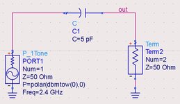
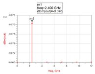
When I plotted the dBm(RF_IN) I obtain -9 dBm right after the RF source which is set at 0 dBm (see images below) . I do not understand why I did not obtain 0 dBm in the plot.
"dBm" function assumes that the Voltage over the Impedance is 50 Ohm but your case is different.
If you know the Impedance when you look into the circuit, you have to use dBm(RF_IN,Impedance).
But there is simpler method. Use P_Probe element to measure the Power that gets into the circuit.
"dBm" function assumes that the Voltage over the Impedance is 50 Ohm but your case is different.
If you know the Impedance when you look into the circuit, you have to use dBm(RF_IN,Impedance).
But there is simpler method. Use P_Probe element to measure the Power that gets into the circuit.
So there is a Mismatch between the Source and the Circuit.
Because 0 dBm is Available Power from the Source. Not Entered Power.
If you design a good matching circuit, this entered power will be same as Available Power.
So there is a Mismatch between the Source and the Circuit.
Because 0 dBm is Available Power from the Source. Not Entered Power.
If you design a good matching circuit, this entered power will be same as Available Power.
Thank you for your answer. I have managed to increase the value to 0.9 mW by adding a microstrip line in series with an inductor in series with a resistor. Is this configuration valid since I have not based it on any available matching circuit configuration ( I just added them arbitrarily)?
This site uses cookies to help personalise content, tailor your experience and to keep you logged in if you register.
By continuing to use this site, you are consenting to our use of cookies.