Continue to Site

Welcome to EDAboard.com

Welcome to our site! EDAboard.com is an international Electronics Discussion Forum focused on EDA software, circuits, schematics, books, theory, papers, asic, pld, 8051, DSP, Network, RF, Analog Design, PCB, Service Manuals... and a whole lot more! To participate you need to register. Registration is free. Click here to register now.

Keysight ADS, EM Cosimulation doesn't place pins

Status
Not open for further replies.

goonballoon

Newbie
Joined
May 30, 2022
Messages
5
Helped
0
Reputation
0
Reaction score
0
Trophy points
1
Activity points
48
Hello, I am designing a simple microwave amplifier and am attempting to use components from the RF_Passive_SMT library to do an EM-Cosimulation.

I can place the component in the schematic and layout, but when I try to generate the EM-cosimulation layout, the ports for the device are not included.
1653886860561.png


1653887383204.png


This is the layout I built.
Note that it appears there are open connections, but I get the same results when the capacitors in question are wired to where the schematic expects them.
1653887286808.png

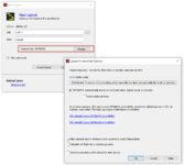
The partitioning settings are correct as far as i know.
1653886994170.png


Here is the autogenerated EM-cosimulation layout.
1653887069219.png


Any help would be much appreciated, thanks!
 
Last edited by a moderator:

Disclaimer: I usually use cosim with hand-routed layout, not auto-generated layout from schematic components, so my thoughts might be wrong.

It seems that the difference between "working" components like R10 and "defective" components like C15 is the broken connectivity shown by the flight lines. I would try to fix that by manually routing a trace between the microstrip component pin position and the SMD component pin position. My best guess is that your SMD will be included in cosim as soon as that connection is properly established in layout.

There is also a setting in ADS to decide what connectivity check is done, nodal or layout. This might be relevant to your case also. It is not relevant to my ADS EM work with "handmade" layout that has no nodal connections anyway.
 

Attachments

  • ads_conn.png
    ads_conn.png
    68.6 KB · Views: 113

Hey Volker, thanks for writing

My note was unclear but I was trying to say that manually routing the trace from the microstrip to the SMD does not solve the problem.

I have messed around a bit with the WYSIWYG setting as well but to no avail. I will continue to explore that option.

I am interested in what you mean by hand-routing, is there an alternative way to co-simulate?
 

I am interested in what you mean by hand-routing
I mean layouts that are based on simple polygons (e.g. from Gerber import) instead of predefined elements (microstrip models) that provide artwork + pins.
--- Updated ---

I was trying to say that manually routing the trace from the microstrip to the SMD does not solve the problem.

But does it solve the connectivity problem, or do you still have flight wires? I wonder if your C15 might have pins on the wrong layer.
 

Have you ever checked " Landing Layer" of the component ? If Landing Layer is different than you've been using, ADS does not take that into account.
Look at Properties of the component.
 

But does it solve the connectivity problem, or do you still have flight wires? I wonder if your C15 might have pins on the wrong layer.
It does not remove the flight wires, so the pins may indeed by on the wrong layer. This is a read only library though, so I can't change the pin layers. Any suggestions for a workaround?

Have you ever checked " Landing Layer" of the component ? If Landing Layer is different than you've been using, ADS does not take that into account.
Look at Properties of the component.
I do not see where to check landing layer of any component. Looks like maybe this is a smart mount feature? I am not using smart mount
 

Can you show the component properties dialog of C15? There might be some layer settings.

I have since renumbered them, here is the layout properties
1654063668386.png


The schematic "info" tab has some layers info but I do not think these are the layers that appear in layout, because nothing is highlighted when I cycle through different layer views in layout.

1654063782648.png


The SMD has a cond(1):drawing layer, a bond:drawing layer, and a package:drawing layer as far as I can tell
 

This is not the dialog that I meant. Please double click on C15 and show the dialog with settings for C15.

It seems that your SMD is not drawing on layer "cond", but there must be some setting to change that. The "SMT_Pad" block is only valid for some elements, other elements might have different ways to set layers. Often there is a layer setting in the element parameters then.
 
Last edited:

Are only KEMET Component used on whole layout ? ? Since the others are compatible, why this one does not have any layout information ? Try with Murata in order to see the problem.
 

Strange, what you showed should work to redirect artwork to layer cond.

You can also try this workaround:
in EM stackup, map layers cond and bond to the same stackup position. This way, pads and pins on layer bond will appear on the same stackup position as your microstrip elements. I think this should work.
 

Status
Not open for further replies.

Part and Inventory Search

Welcome to EDABoard.com

Sponsor

Back
Top