Continue to Site

Welcome to EDAboard.com

Welcome to our site! EDAboard.com is an international Electronics Discussion Forum focused on EDA software, circuits, schematics, books, theory, papers, asic, pld, 8051, DSP, Network, RF, Analog Design, PCB, Service Manuals... and a whole lot more! To participate you need to register. Registration is free. Click here to register now.

Keying transmitter from an external cirquit. Ground loop question

Status
Not open for further replies.

neazoi

Advanced Member level 6
Joined
Jan 5, 2008
Messages
4,122
Helped
13
Reputation
26
Reaction score
15
Trophy points
1,318
Location
Greece
Activity points
36,951
Hi,
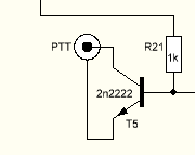
I want to key a transmitter using an external circuit. Usually the transmitter is keyed by grounding one of it's pins in a socket it has.
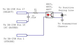
I want to avoid ground loops and the classic solution is to key the transmitter using an opto-isolator.

However will this simple circuit shown work?
Notice that the emitter is not connected to the ground of the external keyer circuit, but it is brought to the plug which connects to the transmitter. The outer shell of this plug is connected to the transmitter ground.

Will this circuit work?
 

Attachments

  • Capture.PNG
    Capture.PNG
    2.1 KB · Views: 77

Hi,

every current needs a loop to flow. We can not see the loop for the base current.

Klaus
 

    neazoi

    Points: 2
    Helpful Answer Positive Rating
It is the ground of the transmitter, it will flow to this one. It grounds through the connector to the transmitter ground. This ground is different from the keying circuit ground (not shown here).
Can positive voltage energize the base of the transistor from the external keyer circuit but instead use the ground of the transmitter and not the keyer, at it's emitter?

An opto-isolator works this way, but of course there is no direct current connection to the base of it's photo transistor.
 

The 'loop' is actually two loops. One is the keying current between collector and emitter, the other is the keyer loop between base and emitter. Both have to be present before the transistor conducts so the answer is no, if there is no common ground at the emitter it will not work, even if the potential between individual grounds is small.

Brian.
 

as per comments above, you really need to draw / provide the WHOLE circuit if you want any sort of useful answer ....
 

Hi
It is the ground of the transmitter, it will flow to this one. It grounds through the connector to the transmitter ground. This ground is different from the keying circuit ground (not shown here).
Can positive voltage energize the base of the transistor from the external keyer circuit but instead use the ground of the transmitter and not the keyer, at it's emitter?
A loop is a loop, closed current flow like in a circle. Current can not flow in one way (from A to B), it always needs a return path.
We can not check this.

I recommend to draw a sketch (at least for your own) and check if the current can flow in a loop.

Klaus
 

    neazoi

    Points: 2
    Helpful Answer Positive Rating
The 'loop' is actually two loops. One is the keying current between collector and emitter, the other is the keyer loop between base and emitter. Both have to be present before the transistor conducts so the answer is no, if there is no common ground at the emitter it will not work, even if the potential between individual grounds is small.

Brian.
How these opto-isolator keying circuits work then?
Can't the same effect happen with a current present at the base? Maybe instead or a single base resistor a potential divider with the middle point to be connected to the base, so as to "close the loop" on the keyer side?
What if I use a mosfet (2n7000) instead? Will it do the same with a voltage present at it's gate, or it won't work as well?
 

Attachments

  • external-content.duckduckgo.com.jpeg
    external-content.duckduckgo.com.jpeg
    26.2 KB · Views: 69
Last edited:

Hi,

Here you have two loops .. sadly you just show snippets thus we have a lot to guess:

* Control loop:
Positive_Supply - switch - DB25_pin17 - R1 - LED - DB25_pin1 - negativve_supply

* Transmitter loop:
positive supply - pullup - p1_upper - collector - emitter - p1_lower - negative_supply

Klaus
 

For this application, think of the optocoupler as being like a mechanical relay. There is no need for the contacts to be connected to the coils, they are electrically isolated.

If you use a transistor you need to 'push' current into the base for it to conduct between collector and emitter, that means you have to provide a voltage source to lift the base to a higher (~0.6v) voltage than the emitter and you can't guarantee that if the emitter itself could be at any voltage.

Worst cases are the keying ground is >0.5V higher than the keyed ground so the transistor starts to conduct when you don't want it to or the ground is more than a few volts lower than the keyed ground and it causes breakdown of the B-E junction.

Brian.
 
  • Like
Reactions: neazoi

    neazoi

    Points: 2
    Helpful Answer Positive Rating
Status
Not open for further replies.

Similar threads

Part and Inventory Search

Welcome to EDABoard.com

Sponsor

Back
Top