Continue to Site

Welcome to EDAboard.com

Welcome to our site! EDAboard.com is an international Electronics Discussion Forum focused on EDA software, circuits, schematics, books, theory, papers, asic, pld, 8051, DSP, Network, RF, Analog Design, PCB, Service Manuals... and a whole lot more! To participate you need to register. Registration is free. Click here to register now.

[SOLVED] junebug pickit 2 error during entering into degug sesion

Status
Not open for further replies.

blind_man

Member level 3
Joined
Feb 26, 2005
Messages
56
Helped
10
Reputation
20
Reaction score
10
Trophy points
1,288
Location
Romania
Activity points
1,646
junebug pickit 2 error during entering into debug sesion

Hello,

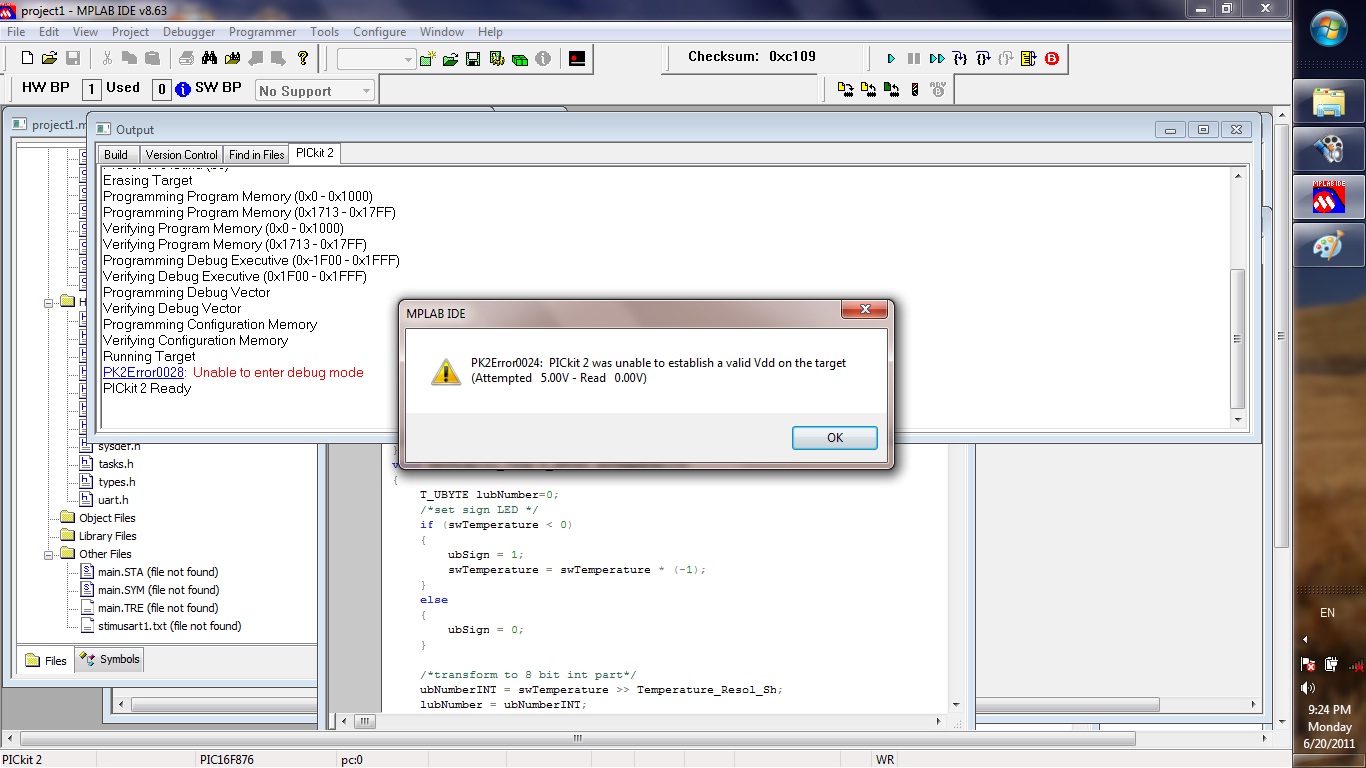
I have build PICkit 2 lite clone and later I update the project to Junebug version of PICkit 2 and I have PK2Error0024 error during enter in debug session.
I have measured the voltage on VDD and it is 4.3V
Does have anybody why I have this error?

The programming is working fine(read/write).
During troubleshooting the test are passed except the first test, not been able to control VDD voltage. Only control is ON/OFF for VDD because I think I do not have the part of the schematic doing that.
Do I need to build full pickit clone in order to debug?
**broken link removed****broken link removed**
 

Hi,

Have built a similar clone and sure I ran debugger ok, though only keep it as backup to my genuine Pk2.
Seem to remember Blueroom says Junebug does debugger

What is the USB voltage from your PC, is it a desktop or a laptop which can cause a problem with their usb voltages being low to start with.
The D2 diode 1n5817, did you use that type which has a voltage drop 0f 0.2v or just any old diode which can drop the voltage by 0.7v.

Have you tried to enter dubugger with the target circuit powered by an external good 5.0v source ?

Your attachments do not open , listed by EDA as Invalid
 

I have attached as pictures:

The voltage on USB port is 4.8. The rest of the voltage it is lost on the p-channel MOSFET and diode. The drop voltage on D2 is 0.2V.
I have not tried with external voltage yet, because it on the first try I have lite version of pickit 2 without part with Q2 and Q5.
 

Hi,

What might be happening is that your target circuit is trying to take too much power or has a short circuit.
Best if you measure the current running out from the Pk2 to your target board.

If its well under 30ma, say a pic chip and a lcd etc then doubt you have a problem there.

What you can try is this -

D2 function is only needed when you connect your Pk2 to a target cicuit that has its own power source.
D2 blocks the target boards power from running back into the USB +5v line.

If you do not have any power direct to your target board, then I would simply bypass D2 so the target board will get the full 4.8v from the USB line and hopefully the PK2 will sense a higher voltage to allow it to run.
 

What might be happening is that your target circuit is trying to take too much power or has a short circuit.
Best if you measure the current running out from the Pk2 to your target board.


If its well under 30ma, say a pic chip and a lcd etc then doubt you have a problem there.

What you can try is this -

D2 function is only needed when you connect your Pk2 to a target cicuit that has its own power source.
D2 blocks the target boards power from running back into the USB +5v line.

If you do not have any power direct to your target board, then I would simply bypass D2 so the target board will get the full 4.8v from the USB line and hopefully the PK2 will sense a higher voltage to allow it to run.

I will measure the current consumption today. The target has a 16f876 and 3 LEDs. I will power up the target without the PICKIT and measure the current. I can also try it the target connected to power supply, before I short D2. Do you know what is the threshold in order not to have this problem?

---------- Post added at 08:29 ---------- Previous post was at 08:05 ----------

Can it be possible that the Q5 has RDS(on) =14Ohm to mush? I have see another clone use IRF9530 ( Rdson = 0.3ohm) or IRF9Z34 (0.1ohm)?
 

The only figures I have seen are in the PK2 user guide - though refering more to the programming side, assume it applies to the debug.
Current through a full Pk2 25ma voltage min 4.75v.

Would also check the current being drawn by your circuit when powered by the Pk2, it may only show up a problem when the debugging lines are connected etc.
 
I must rectify, I think I have give you wrong information on initial post that I have 4.3V:
pickit2 with target:
voltage USB: 4.92V
after p channel tz : 4.88V
after D2 : 4.62V
If I remove the target I have 4.92 after D2
Power consumption of target <10mA
Power consumption of target +pickit2 external supply, 20mA
If I connect an external supply:
- voltage usb 4.92V
- voltage after p-channel Tz 4.99
- voltage D2 5V

And I have the same error.
 

Hi,

Well all those readings sound fine, so if you still get the message 024 I would suspect that the +5v at D2 / Ouput connector is loosing voltage on its way back to the voltage sense on RA1 pin 3 via the 4k7 resistor.

? - you say it programs the pic chip ok, when you do that is the pic chip connected on its own to the Pk2 or is it still in the target circuit ?
 

I do not understand, on the RA1 pin 3 it is the voltage that I set into pickit2 program, I have measured on pin. And the programing is Ok. I programed the target (pic16f876) remove the power , remove the pickit2 and place them again and verified ok. The chip it is on the target , I have ICSP conection on the target. So it writes ok with the pic in the target.
I am starting to think that pickit2 junebug has no capability of debuging, only full version with VDD controlled with operational and a n-channel tz.
Is there any software setting in target firmware to enable the debuging?
 

Hi,

I have just connected my Microchip Pk2 to my dev board and run a program on it with debugger ok.

Then powered off and closed Mplab down, restarted with the diy Pk2 board, rebuilt the progect and started debugger without any problems.

Other than the Mplab settings for the Pk2 not aware of any other things you can change.

The Junebug is just 2 boards together, a Pk2 clone and the 1320 tutor board - have never used them but they should work together or independantly.

That Junebug Pk2 uses a few more parts than the version I built, basically its identical to this diagram with VDD going out via just D2 .

The only remaining thing to ask /check is what version of the Pk2 have you got programmed into the 2550 and what version of Mplab are your on.
am using Pk2V023200 with Mplab v 8.70
 

Attachments

  • pickit2_Lite.pdf
    44.6 KB · Views: 80
I will sent you the firmware version and mplab version when I will get home tonight.

So you have pickit2_lite and the debuger works fine?

If so it must be a problem on the debuger.

I have the pickit 2 and the target, the pickit 2 is directly connected to target.
Do I need aditional hardware ? Do you have an ICD header?
 
Last edited:

Hi,

Yes the diy clone works well in debug mode as you can see from the attached screenshots.

The 876 should run fine, no headers or anything special at all - I always try and use chips that are 100% debug compatible.

Vdd /Vss/RB6/7 should be direct connections and Mclre should be connected as shown in the Pk2 User Guide with res/cap and diode or res.
Are you using a very large electo capacitor on the Vdd of your target board ?

Pin3 RA1 of the 2550 is in Input mode, it reads the Vdd voltage either from the external source or it own power.
It should measue Vdd voltage at pin 3.
You cannot adjust Vdd voltage as your clone does not have the required circuitry, but thats not a problem as you have 5v.

All the settings for changing anything to the Pk2 are in Mplabs Debugger and Pk2 'Settings' drop down folders.
Assume you have got the Vdd switched on to 5v , if you have Q2 fitted you need to do this otherwise internal Vdd is switched off.

You say you can program the chip ok, but is this done with Pk2 Application V2.61 - if so, have you tried programming the chip by Mplab ? ( you must close program v2.61 before trying PK2 with Mplab )
 

Attachments

  • ScreenShot002.rar
    294.3 KB · Views: 79
I am using the Mplab version 8.63 and firmware PK2V023200.hex.
I have erase the pic18f2550 and download again the firmware with multiprogrammer(JDM based ). One idea was to reset the calibration value, stored, but again same error message.
The programing with mplab also is working in debug mode and also if you select programmer from menu.
On the target I have directly connected the vdd, vss RB6 and RB7. MCLR is pull up with 1k resistor to vdd. There is also an electrolitic capacitor 47uF on VDD.
 

Hi,

I program and debug using the programs default settings as downloaded, nothing changed.

So you can program with your Pk2 clone under MPlab control but not run debugger ..??

Can you program ok with Pk2 V2.61 stand alone program.

Your target circuit may be working but it is not ideal.

The pull up resistor on its own should be more like 10k when the target is run on its own, however you must add a couple more parts if you want to program or debug in circuit.
See the ICSP pages of the PK2 User Guide for the actual circuit diagram.

The 47uf in your circuit may be too high for ICSP, try it without that cap.
When 5v is turned on vdd is temporarily shorted by the 47uf while it charges, if the Pk2 samples Vdd during that time it could get the wrong reading.

Its also normal to have a 100nf closely fitted across the Vdd and Vss pins of all ics.

Other than that am at a loss to say whats wrong ...??
 
Every think is working except it is not enter into debug mode. I can program also with pickit stand alone program, it looks ok. I will try to add extra parts missing.
 

Hello,

I have replaced 1Kohm resistor with 10Kohm and I have added 470ohm in series with MCLR and I am glad that I managed to get pass the error 24. But now I have error 28. We are making progress after 2 weeks.
 

Hello,

I have replaced 1Kohm resistor with 10Kohm and I have added 470ohm in series with MCLR and I am glad that I managed to get pass the error 24. But now I have error 28. We are making progress after 2 weeks.

Hi,

Well thats good news, though did you add the 100nf cap to the Mclre resistors - it might make a difference. anything 47nf to 220nf will probably work ok.

Error 028 covers a vast amount of possible problems - again the Pk2 user guide pages 56.57 details them.

However worth checking again, no other copy of Mplab or PK2 V2.61 running at the same time.
Its quiet easy to confuse Mplab /Debugger and get error 28 so -
Unselect Debugger, close down Mplab, restart mplab and build your project, then Select Debugger PK2.

Hardware wise, again check Mclre. Vdd , Vss connections, have you removed that 47uf, it might make the difference.
Nothing else connected to Rb6 or Rb7 than the programming lines ?

Think you are coding in C which i cannot help with, but check you Config statements that all its correct, as indicated in the Pk2 guide.
 

hi,
Thank 's help. I have changed quart from 16MHz to 4Mhz and problem has been solved. Now the I can debug. So the conclusion: It was a combination of problems:
1) calibration value has been stored and a lower value had been check in the debugger firmware
2) the ICSP interface has not ok, specily the MSLRE. 10kohm instead 1k and a missing capacitor. But most important isolation of MSLRE with a resistor 470ohm.
3) the quartz frecv was to high in order debuger to handle the data.
4) configuration bits are very important:
__CONFIG(XT&DEBUGDIS & WDTDIS & LVPDIS);
used for pic16f876.
There still a problem on my debugger, the voltage on MSLRE is 11.42V to small.

Can you please measure what is this voltage on your pickit?
 

hi,

There still a problem on my debugger, the voltage on MSLRE is 11.42V to small.

Can you please measure what is this voltage on your pickit?


Hi,

Sounds as if you have made good progress, what is the problem with Mclre - its normally at +5v to run, 0v to Reset and 12v approx to program.

Other than when programming the chip with debugger do not know if Mclre is held at anything other than 5v.

On my real Pk2, the test routine reports 11.9v but measured at pin1 with a chip in it shows 9.4v ?!?
The Clone as above but measures 11.84v

Both program and debug fine.
 

Status
Not open for further replies.

Similar threads

Part and Inventory Search

Welcome to EDABoard.com

Sponsor

Back
Top