saharnaz
Newbie level 1

- Joined
- Apr 17, 2014
- Messages
- 1
- Helped
- 0
- Reputation
- 0
- Reaction score
- 0
- Trophy points
- 1
- Activity points
- 8
Hello
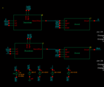
I am trying to make a jk flip flop with cadence and designed it with cadence, exactly like what I saw in the internet. but it's not working!I have attached a picture of my circuit. inside the blocks, are the 3 input nand and 2 input nand circuits which are fine and working perfectly when tested outside this circuit. I have set j and k both as vdd (logical 1) so it should toggle whith each clock rise. but it doesn't. can you tell me what I'm doing wrong?
Thank you very much
Saharnaz

