Continue to Site

Welcome to EDAboard.com

Welcome to our site! EDAboard.com is an international Electronics Discussion Forum focused on EDA software, circuits, schematics, books, theory, papers, asic, pld, 8051, DSP, Network, RF, Analog Design, PCB, Service Manuals... and a whole lot more! To participate you need to register. Registration is free. Click here to register now.

jdm programer problem

Status
Not open for further replies.

ahmadezz

Newbie level 3
Joined
Oct 31, 2011
Messages
4
Helped
0
Reputation
0
Reaction score
0
Trophy points
1,281
Activity points
1,316
hi every body
first , i am an engineering student , and i'm beginner in these stuff .
i bought a velleman programmer , but there is something wrong in it , so i just need
to build my own programer right now , just for learning .
this is what i did.
c1.png

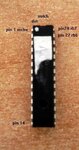
MCLR----TxD ::: there is a white wire maybe its not showen.
DATA(RB7)-----DTR + CTS
CLK(RB6)------- RTS

100 ohm Resistor


and the power source as you see
3 * 1.5 v battry

my pic : 16f876a

and i tried to do this one
**broken link removed**

if there are any way to make it work??
i just have a resistors and capacitors :)
and i'm really sorry for this question :smile: but just like i said , iam a beginner .
thanks alot.
 
Last edited:

My friend use this and put real +5V not that thing with thise batteries!

picprog_16F876.gif

Use IC-Prog software

These changes in the default settings are required to make everything work:
- Change controller type to 16F876
- Settings > Hardware > Windows API
- Settings > Hardware > I/O Delay = 1 (important!)
- Settings > Options > Programming > Verify during programming (If verify fails for a single byte, IC Prog seems to rewrite it)


Later if there is time and some money, build PICKit2 programmer or buy it.

:wink:
 
Hi,

Well from what I can see you have wired the chip the wrong way round.

If you look at page 4 of the 876A Datasheet it shows the correct pin diagram - this view is looking down onto the chip as in your picture.
Pin 1 has that little hole/ indent against it, the same end as the larger end notch.

Cannot say if it has damaged the chip, but if +12v has gone onto it there is a chance it is damaged.

Also there are two connections for +5v pin 8 and pin20, with 0v going to just pin 19.


Have never used that circiut , it may work if you are lucky.

What model Velleman programmer do you have and whats wrong with it - it could be a simple fix...?


Edit oppps - sorry that should be pin8 and 19 go to 0v and pin 20 to +5v
 
My friend use this and put real +5V not that thing with thise batteries!

View attachment 63651

Use IC-Prog software

These changes in the default settings are required to make everything work:
- Change controller type to 16F876
- Settings > Hardware > Windows API
- Settings > Hardware > I/O Delay = 1 (important!)
- Settings > Options > Programming > Verify during programming (If verify fails for a single byte, IC Prog seems to rewrite it)


Later if there is time and some money, build PICKit2 programmer or buy it.

:wink:

thank you :)
i will try .

---------- Post added at 09:47 ---------- Previous post was at 09:37 ----------

Hi,

Well from what I can see you have wired the chip the wrong way round.

If you look at page 4 of the 876A Datasheet it shows the correct pin diagram - this view is looking down onto the chip as in your picture.
Pin 1 has that little hole/ indent against it, the same end as the larger end notch.

Cannot say if it has damaged the chip, but if +12v has gone onto it there is a chance it is damaged.

Also there are two connections for +5v pin 8 and pin20, with 0v going to just pin 19.


Have never used that circiut , it may work if you are lucky.

What model Velleman programmer do you have and whats wrong with it - it could be a simple fix...?


Edit oppps - sorry that should be pin8 and 19 go to 0v and pin 20 to +5v

thank you , but no its in the right way but the picture is so bad .

and my vellman is K8076 .
its problem the red light is not lighting , but if i touch the transistor or resistor wich before it in the circuit , it will light up.

the other lights is working good , the red led jop is to resteart the pic -- MCLR.

and actully i think my pic is broken , i will buy a new one today .

thank alot guys.
 

thank you , but no its in the right way but the picture is so bad ..

Hi,

Are you sure, I know my eye sight is poor but that still looks the wrong way round to me.

That single connection on the left side, is that supposed to be Mclre Pin1 ? if so its the wrong end or side.

and my vellman is K8076 .
its problem the red light is not lighting

Assume thats a kit you have built, it seems a good circuit and should work ok, what have you done to test it, have you got a multimeter ?
 

That single connection on the left side, is that supposed to be Mclre Pin1 ? if so its the wrong end or side.
yes its mclr !! isn't the right way ??


what have you done to test it, have you got a multimeter ?

the programme wich included with it can test every thing in the circuit then show the result as LED light up .
and i have multimeter , and checked the circuit with it , no problem ! every thing works OK !
 

yes its mclr !! isn't the right way ??

No, not as i'm looking at it, as I mentioned before check the diagram in the 876A datasheet.


the programme wich included with it can test every thing in the circuit then show the result as LED light up .
and i have multimeter , and checked the circuit with it , no problem ! every thing works OK !

?? but you said in your first post it was not working ?

Just wonder if its because you wired the Zif socket/connector incorrectly for the 876A chip.
If its like the breadboard layout then its wrong ..
 

Attachments

  • 876.jpg
    876.jpg
    59.4 KB · Views: 69

No, not as i'm looking at it, as I mentioned before check the diagram in the 876A datasheet.


?? but you said in your first post it was not working ?

Just wonder if its because you wired the Zif socket/connector incorrectly for the 876A chip.
If its like the breadboard layout then its wrong ..

https://ww1.microchip.com/downloads/en/devicedoc/39582b.pdf

this is the datasheet
and it says that pin 1 is the mclr , and this ia what i did .


and about the veelman !
i Wondering what is the problem , just like i said the components are good , but the red light doesnt work , unless i touch the components with my hand !!!!
 

Hi,

One last thing to prove the point to you .. on my picture there is a white mark against Pin 1, I put it there to easily identify pin 1 as Microchips mark is just a little indentation in the black plastic and can be hard to see in poor light.
On the datasheet its looks like the degree sign just to the left of the ' ° 1 '

Look at each corner of the top of your chip, one corner will have this little indentation, its the end of the chip that also has the little half moon identation - that is pin1 and it should agree with my photo.

Hopefully you will see that from your photo you have connected pin 28 as pin1.
 

.......................
and my vellman is K8076 .
its problem the red light is not lighting , but if i touch the transistor or resistor wich before it in the circuit , it will light up. the other lights is working good , the red led jop is to resteart the pic -- MCLR. and actully i think my pic is broken , i will buy a new one today ...................
i too have a doubt that the 16F876 is mounted on bread board with the notch facing upwards.
please follow the advise of WP100.
Please refer to sch in your reference manual. if it is responding with finger on base of T2 and not with base of T1,
perhaps T1 is faulty.
unless T1 conducts, T2 wont conduct. Simple way is to connect top side of R9 to Vcc or +Vpp.
then red lamp should glow. if once it glows, the circuit would work. possible reasons, either D4 shorted or T1 faulty with base-emitter break.
 

Status
Not open for further replies.

Similar threads

Part and Inventory Search

Welcome to EDABoard.com

Sponsor

Back
Top