Continue to Site

Welcome to EDAboard.com

Welcome to our site! EDAboard.com is an international Electronics Discussion Forum focused on EDA software, circuits, schematics, books, theory, papers, asic, pld, 8051, DSP, Network, RF, Analog Design, PCB, Service Manuals... and a whole lot more! To participate you need to register. Registration is free. Click here to register now.

Issues with loop stability of an LDO

Status
Not open for further replies.

quaternion

Full Member level 4
Joined
Nov 12, 2006
Messages
212
Helped
17
Reputation
34
Reaction score
7
Trophy points
1,298
Location
Cairo , Egypt
Activity points
2,828
Loop stability

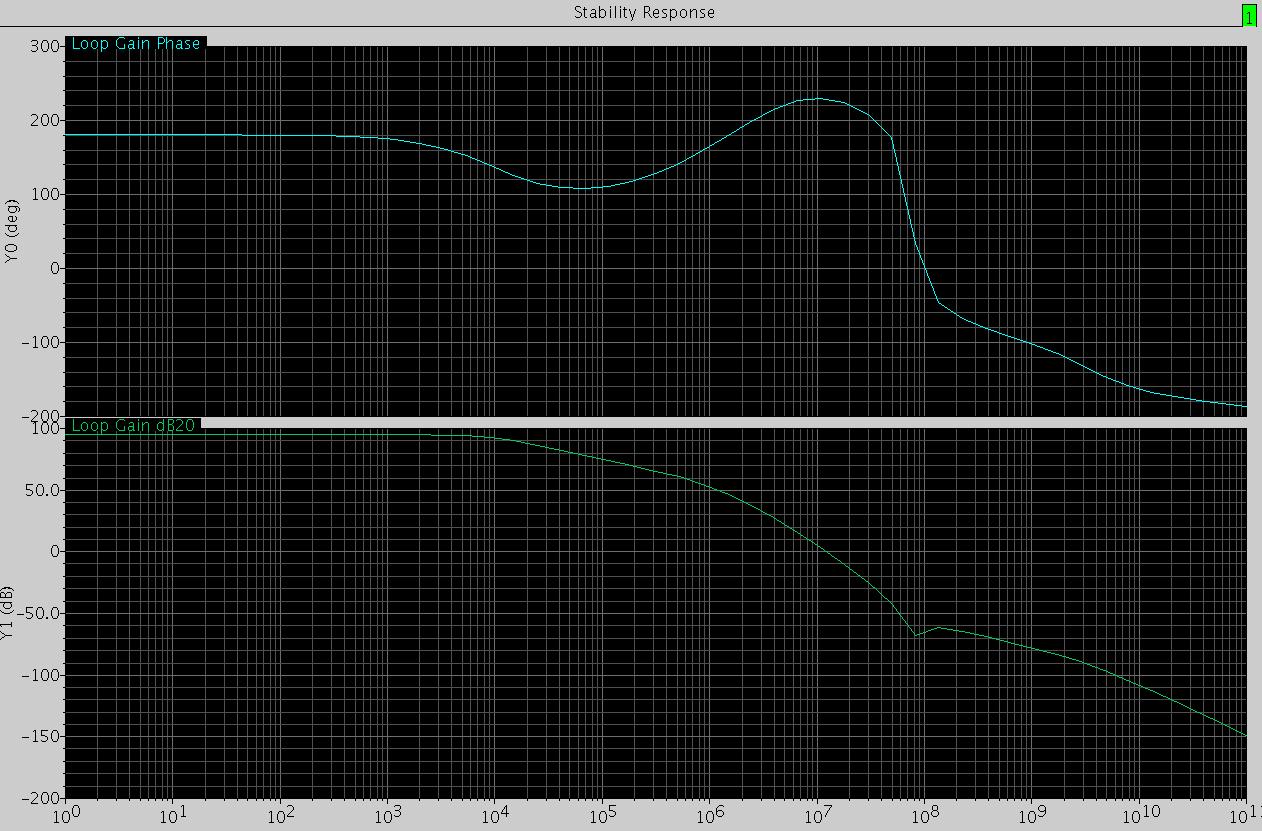
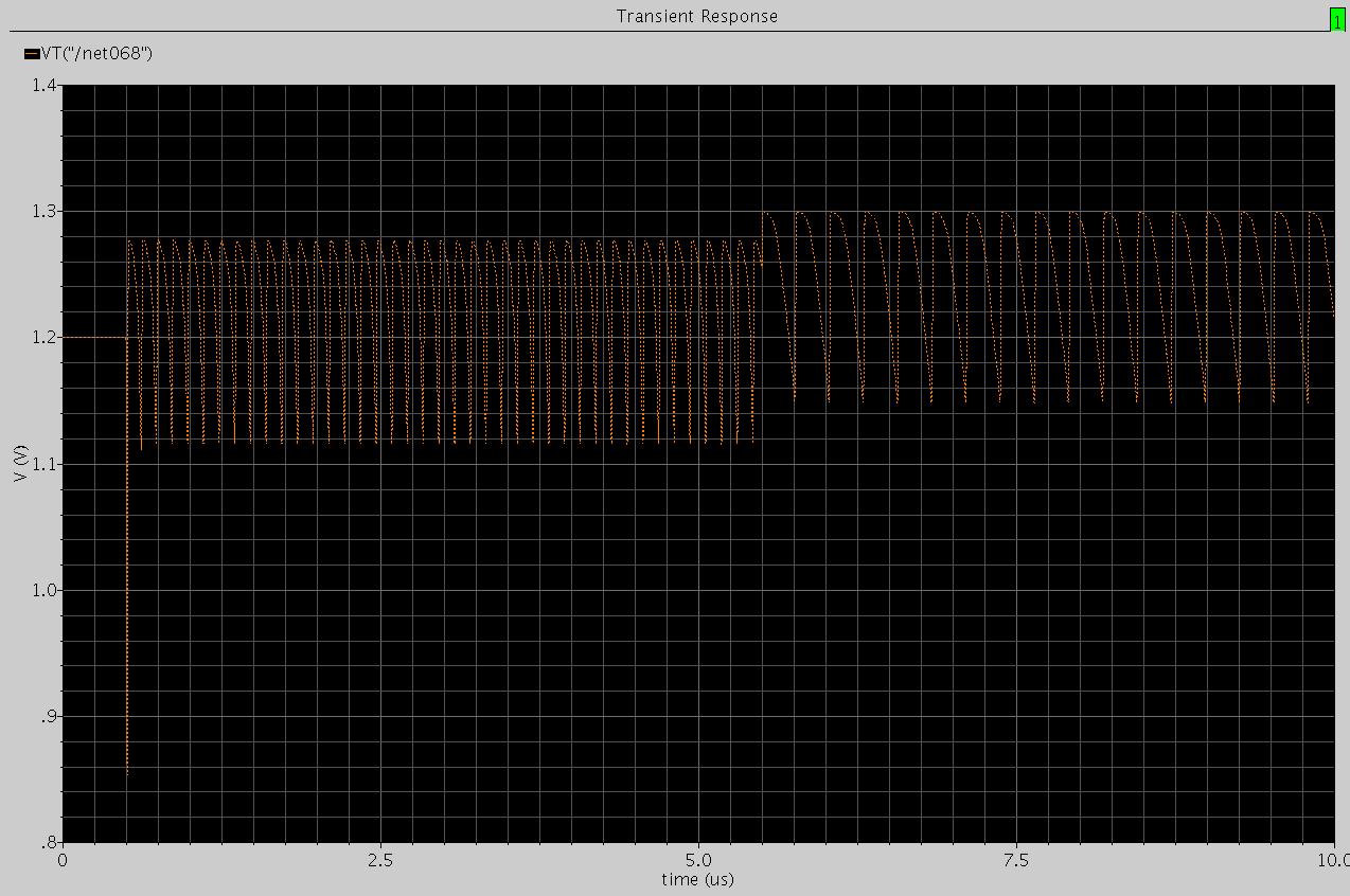
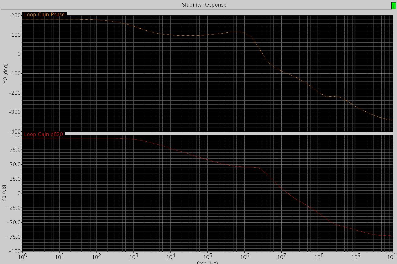
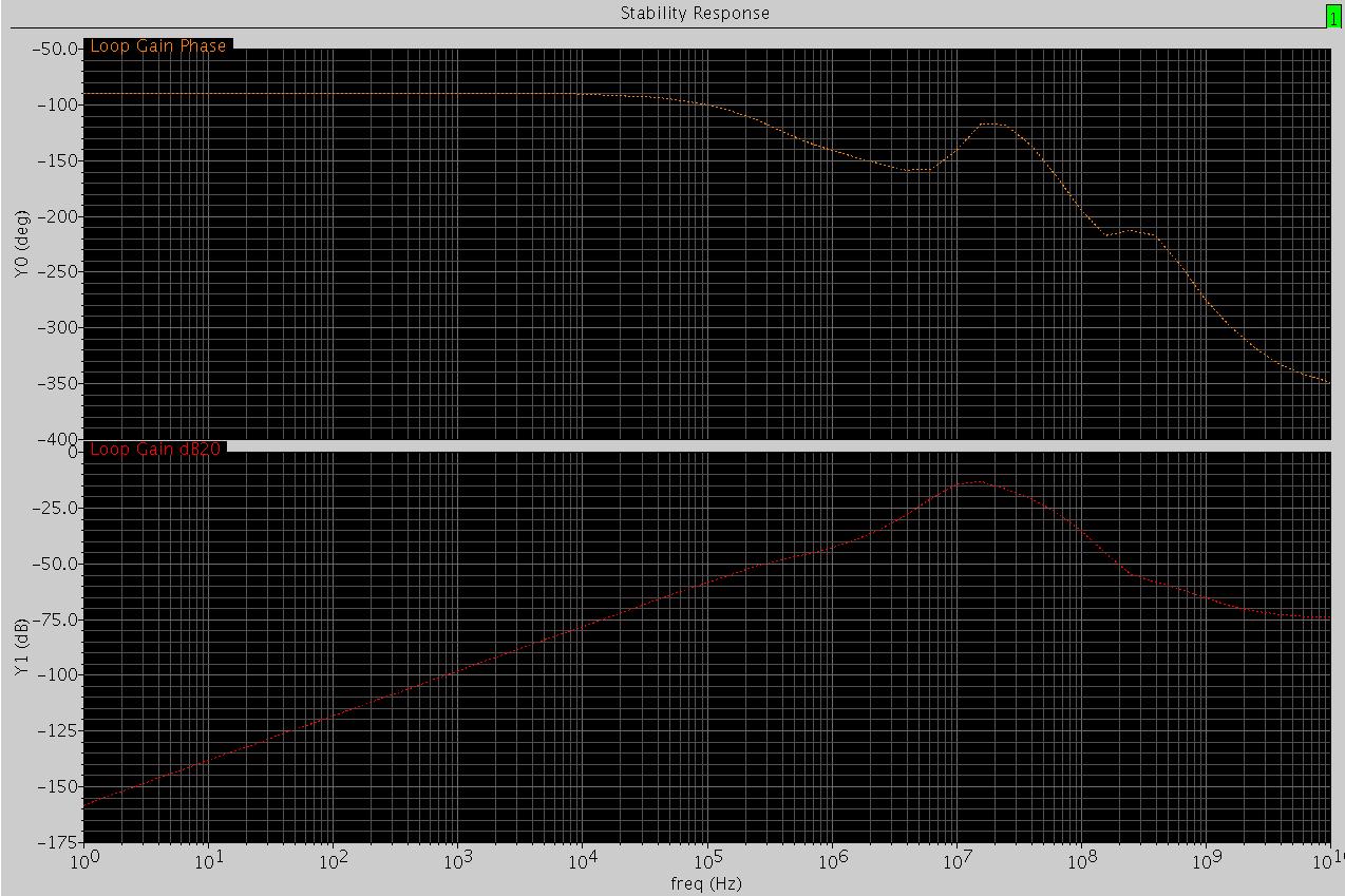
This picture shows the loop gain & phase of my LDO , as shown the phase doesn't get apart from its initial value by more than 180° (either in positive or negative phase),but the transient response shows an oscillation.
[this response is at no load, at full load ,also the phase is within the previous limit]
Why does it oscillates in transient ?
Thanks.
 

Re: Loop stability

Im no expert for LDO design, but I basically doubt, that the shown phase response can correspondend to the amplitude response. May be the loop gain measurement setup is wrong somehow.
 

Re: Loop stability

I am using active feed forward that adds zeros in the transfer function ; that is the reason for getting phase increase(reversing the direction) with frequency increase.
 

Re: Loop stability

Phase elevation as such is a common means, but I doubt that you can have phase elevation and -40db/decade gain slope at the same time.
 

Re: Loop stability

Could it be two RHP poles ?

Note: I get this response from the schematic using iprobe and stability analysis it isn't from a behavioral modeling ; parasitic poles and zeros surely exist.
 

Loop stability

maybe u should post schematic and test setup.
 

Re: Loop stability

The schematic


I test transient by editing the ipulse source so that it generates a current pulse with rise and fall of 100p and duration 5u and current value = 5mA .
 

Re: Loop stability

Hi
I don't think the stability analysis is right.
The phase up but the magnitude is still roll off, and the phase go up more than 90 degree, it is so wired.......because no inductor in here..

Where the stb probe you added ? ?
 

Re: Loop stability

As mentioned in former replies, probably the loop gain simulation is not correct.
Here is a short summary of important points:
1.) The loop has to be opened for feeding in an input signal.
2.) The loop opening must not destroy the bias conditions.
3.) The loop opening must not change the load conditions at the point of cut.

Therefore, some special care has to be taken for finding the proper loop gain.
4.) If you can find a point within the loop which fulfills items 1,2 and 3 you can open the loop and inject a signal
5.) If not, you have to apply a special test procedere which is described elsewhere.
(If you don´t know where, give a short notice)
 

Re: Loop stability

are you getting oscillations noload and fullload both?

can you post the wave form also.

Also I would suggest you to check and tighten the simulation options for your simulator.
 

Loop stability

i have few suggestions:
1- try to increase the accuracy of simulator and number of points in AC analysis
2- try to check stability of the two loops separately first, then cut the two loops together
 

Re: Loop stability

ashish_chauhan said:
are you getting oscillations noload and fullload both?

can you post the wave form also.

Also I would suggest you to check and tighten the simulation options for your simulator.

I uses conservative setting for transient analysis, how could I tighten the simulation for stability & transient analysis(which items of options and their settings).

here is the transient wave form.[note that the 0.5usec before applying the mono pulse the output is right which is 1.2V ]


safwatonline said:
1- try to increase the accuracy of simulator and number of points in AC analysis
2- try to check stability of the two loops separately first, then cut the two loops together

I don't use AC analysis.
I have placed the iprobe at the gate of the pass element and I get the same result.
Then I placed it after branching : once at the lower loop and once at the upper loop.
response for the lower loop

response for the upper loop

What should I conclude from the response of each loop alone ,as the reason of using the lower loop is for compensation??!

Should I do AC analysis instead of the stability analysis to get accurate results?
 

Re: Loop stability

This sounds confusing. You show us a diagram which looks like a BODE graph (gain vs. frequency) and at the same time you tell us that you have NOT performed an ac analysis ? Can you clarify this ?
 

Re: Loop stability

I must confess, that I wasn't motivated to extract the loop structure from the transistor level schematic recently presented. You have been talking of a feedforward structure previously and of two loops in your last posts. Feedforward wouldn't necessarily imply additional feedback loops, to my opinion.

Can you also give an equivalent circuit of the loop structure, not considering transistors, just the gain blocks, respectively control process/controller. This would allow to assign the gain simulations and understand their meaning within the system.
 

Re: Loop stability

Added after 22 minutes:

LvW said:
This sounds confusing. You show us a diagram which looks like a BODE graph (gain vs. frequency) and at the same time you tell us that you have NOT performed an ac analysis ? Can you clarify this ?

Stability analysis enables the plot of the loop gain |A(s)*β| and loop phase < A(s)*β versus frequency.


For FvM :Here is some near representation for the system.
 

Re: Loop stability

May be the name of the analysis performed by your program is "stability analysis", however, if the result is gain resp. phase vs. frequency it is a kind of "ac analysis", isn´t it ?
 

Re: Loop stability

I think you are right , but spectre has also a separate AC analysis.
 

Loop stability

ok, here is another few comments:
1-the output u showed (transient output) is (at least to me) doesn't look like oscillation specially with those sharp edges
2-i think the ripples on the output are due to the current pulses u added at the output (i.e. not oscillation)
3-so if number 2 is true then problem solved :D
4- stability analysis is an AC analysis special to checking stability of closed loops without breaking them (using iprobe to break the loop) so it is just like AC u can for instance increase number of points per decade for more accuracy
5- could u state more info about the lower loop as i think in high frequency it might affect the stability
regards
 

Re: Loop stability

safwatonline said:
i think the ripples on the output are due to the current pulses u added at the output (i.e. not oscillation)
Actually the load is a mono current pulse not pulses.

safwatonline said:
could u state more info about the lower loop as i think in high frequency it might affect the stability
It is a feedforward stage that should add a LHP zero that elevates the phase again to compensate the loop, and the phase elevation appears in the phase response, also i uses the resistor in the figure only as I initially used it but all the results I put were with the resistor in the lower loop has zero value.
 

Loop stability

OK, here are other few comments:
1- try do stb analysis sweeping the load current (i.e. not just no load and full load but several steps), this to make sure that the PM is monotonic
2- try to change the current pulse in the transient to be smaller and see if still "oscillates"
3- what is the frequency of the ripples?
4- what happens at 5.5us?
5- assuming that the only stimulus u added is that mono current pulse, please send the current coming out of the source and the current passing through the Mpass transistor, and the current into the DeCap
regards.

again i think the edges at the output are very sharp, so try to see what makes those sharp transitions
 

Status
Not open for further replies.

Similar threads

Part and Inventory Search

Welcome to EDABoard.com

Sponsor

Back
Top