Continue to Site

Welcome to EDAboard.com

Welcome to our site! EDAboard.com is an international Electronics Discussion Forum focused on EDA software, circuits, schematics, books, theory, papers, asic, pld, 8051, DSP, Network, RF, Analog Design, PCB, Service Manuals... and a whole lot more! To participate you need to register. Registration is free. Click here to register now.

Isp schematic for atmega1281

Status
Not open for further replies.

hobbss

Member level 2
Joined
Oct 18, 2010
Messages
49
Helped
20
Reputation
40
Reaction score
19
Trophy points
1,288
Activity points
1,858
So I found out the hard way that the ATMEGA1281 does not use the SPI pins for ISP (what's that pnemonic about how to spell "assume"?).

I have a second design that I am ready to send to the board house, but would like to confirm that I actually have the ISP pins identified correctly. I am using a AVRISP mkii programmer (6 pin)

As I [now] understand it, the connections should be:

Code:
ISP Connector  ---->  ATMEGA
MISO (pin 1) -------- PDO = PE1 on 1281
MOSI (pin 4) -------- PDI = PE0 on 1281
SCK (pin 3) --------- PB1 on 1281
GND, Vcc -- GND, Vcc.

Furthermore, because I also have an RS-232 transceiver on these pins, I think I need a series resistor on those two lines, between the transceiver and where the ISP connector ties in

Code:
MAX232 --- 1kOhm resistor -----+-----PEx
                               |
                               |
                               |
                           ISP Signal

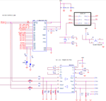
I have attached a schematic describing what I mean.

Does anyone have any experience with the ATMEGA1281 ISP pins?
 

Attachments

  • commsSchematic.png
    commsSchematic.png
    79.8 KB · Views: 90

That is not really what I am talking about. I have a programmer -- an AVRISP mkII that I will use to program the board. I am just concerned that I have PDO and PDI flipped.
 

There is only one place you need to look when you have a question like that (and it should be the first actually) and you can be sure that what is says is valid, not an assumption.

See page 350 of the datasheet www.atmel.com/dyn/resources/prod_documents/doc2549.pdf

You are using TQFP64 (ATMEGA1281), your connection is correct
I have attached a picture

Atmega1281.gif

I don't know the effect of the connection with the rs232 chip, the most secure method is a jumper that selects between programming and uart.
When you use a resistor like that the programmer has to be able to provide the current needed (because of the resistor) to force the value of the pin.

Alex
 

The chip which will be programmed is the slave,

The MOSI pin is Master Output Slave Input so it goes to the "serial data in"
The MISO pin is Master Input Slave Output so it goes to the "serial data out"

Alex
 
  • Like
Reactions: hobbss

    hobbss

    Points: 2
    Helpful Answer Positive Rating
That's what I thought (after checking the data sheet), but just wanted to verify (as I said, having been burnt once).
 

Status
Not open for further replies.

Part and Inventory Search

Welcome to EDABoard.com

Sponsor

Back
Top