Continue to Site

Welcome to EDAboard.com

Welcome to our site! EDAboard.com is an international Electronics Discussion Forum focused on EDA software, circuits, schematics, books, theory, papers, asic, pld, 8051, DSP, Network, RF, Analog Design, PCB, Service Manuals... and a whole lot more! To participate you need to register. Registration is free. Click here to register now.

Isolation To be, or not to be: that is the question

Status
Not open for further replies.

tanbakoo

Newbie level 6
Newbie level 6
Joined
Dec 27, 2007
Messages
12
Helped
0
Reputation
0
Reaction score
0
Trophy points
1,281
Visit site
Activity points
1,382
Hi every body,

when I want to design a system with 28v power input, I have an earth and a 28v return so in many document I can read these must be isolated but in automotive ,vehicle and airplane skeleton and structure is connect to 28v return (I have not a wire for 28v return) so I must connect 28v return wire to structure at the near of system also bonding wire connect to structure so out of system earth and 28v return connect to each other.

so what about my digital and analog GND ? for have a clean GND for CS and RS test and have low emission in RE and CE I was isolate power input so I should be isolate every I/O that consume cost and design time and PCB area and decrease quality of analog interface (specially video input & output)

Finally I have a doubt in my decision... If I can do it without isolation so is very better for me (cost,time,quality,area,...) is there a solution to design system without isolating?
If yes please tell me.
If No and isolation must be used so it is only for DC isolation? I must use capacitor to have a AC connect? only one capacitor or a lot of capacitor? or another kind of connection between digital GND and earth must be used?

Thanks for your attention
 

but in automotive ,vehicle and airplane skeleton and structure is connect to 28v return (I have not a wire for 28v return) so I must connect 28v return wire to structure at the near of system

This makes it sound as though your project is installed in a vehicle. Can you confirm what environment your project is in?

Devices that cannot tolerate electrical noise (or static charge, etc.) should have precautions installed between them and the power supply.
 

It looks like you are only dealing with 28V system and there is no other mains powered system interface. In that case the end product usage should be looked into to what level the earthing has to be done. Whether it is required or not.
You are also talking about the bonding wire here - you need to treat it separately as this in much different than the earthing (or grounding) to the chassis. Bonding is connection between two metal plates to keep them at same potential.
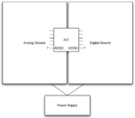
While earthing the power return, care should be taken that there won't be any ground loops. It may be confusing to explain everything in words, so a schematic will be better. Giving you couple of links, where some of these methods are explained well, which you can refer and make use of them.
**broken link removed**
 

Hi every body,
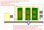
this is block diagram of my system
EMC.jpg
 

Attachments

  • emc_sheet.pdf
    60.2 KB · Views: 114

The 1M resistors and capacitors appear to be a good safeguard. I also picture zener diodes in numerous strategic positions. The reason is because a vehicle moving in air can generate static charge. I think you need to make sure all components will distribute this static charge equally to all other components, so that volt levels match.
 

A) You see 16 question mark near parts in this design please tell your idea about them:
A1) each parts (res or cap) should or should not be used?
A2) value of each part is ok?
A3) Nets at both side of each part is ok?
A4) How many of each part must be used?

B) This section use for isolating every thing so it consume cost,design time,PCB area and
decrease quality of analog signal (specially for analog video, it is very bad)
B1) Is there a solution for removing this section and pass EMC test?
B2) What is the best solution for isolating Analog signal specially for Video and Audio?
 

These safeguards have the purpose of preventing something that might happen. No one can predict whether harm might happen if you omit them. I'm certainly no expert.

Research teams conduct tests of various sorts, to find out whether a product will survive in a real world environment. I picture one man crouching over the prototype, probing different components with an FET-input voltmeter. A second man drives the vehicle.

I'm not sure how they check volt levels in a prototype, because it ought to have the shielding in place. This makes it difficult to apply meter leads.

Examine schematics of projects similar to yours. They may indicate what safeguards are used. Manufactures may prefer to keep such things a secret, of course.

B2) What is the best solution for isolating Analog signal specially for Video and Audio?

Quality coax cables, with sufficient shielding.

Install metal boxes around devices which process these signals.

It may help to give them their own separate power supply.
 

Hi mdyusuf,
your answer is for interior of my system but my problem is for out of my system and when connect it to many systems together in one larger unit such as vehicle. single point connection do not applicable because I have many connection (for example 5) to other systems and I do not know what is the ground topology of them so may be I have many ground loop and noise , ...
 

Status
Not open for further replies.

Part and Inventory Search

Welcome to EDABoard.com

Sponsor

Back
Top