richard_jay
Newbie level 3
Hey,
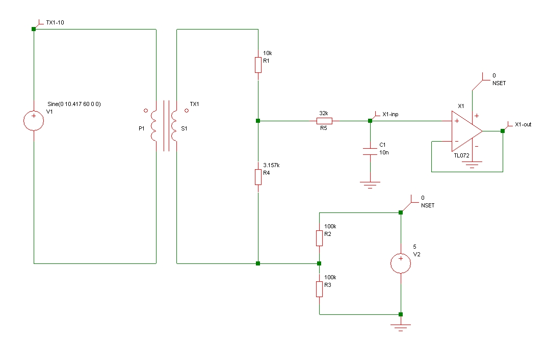
I would like to design a voltage measurement circuit using a step-down or isolation transformer and I would really appreciate some advice on practical implementation of a solution.
The input voltage is nominally 120 V RMS (max 180 V RMS) and an Instantaneous output voltage between 0 - 5 V biased at 2.5 V DC is required for sampling by an ADC.
I have initially considered the type of transformer to employ – isolation or step-down.
Step-down transformers are much more readily available and therefore seem the most appropriate selection.
The data sheets for these step-down transformers tend not to provide detailed design information. They simply state the typical step down voltage (e.g. 120 to 6 V AC) and the current rating (e.g. 58 mA). How do I determine what value of load resistor to select for my application? Where do I begin?
Thanks, Rich