Continue to Site

Welcome to EDAboard.com

Welcome to our site! EDAboard.com is an international Electronics Discussion Forum focused on EDA software, circuits, schematics, books, theory, papers, asic, pld, 8051, DSP, Network, RF, Analog Design, PCB, Service Manuals... and a whole lot more! To participate you need to register. Registration is free. Click here to register now.

isisi software: 4017's VSS and VDD

Status
Not open for further replies.

rascal_141

Junior Member level 1
Joined
Feb 18, 2014
Messages
19
Helped
1
Reputation
2
Reaction score
1
Trophy points
3
Visit site
Activity points
121
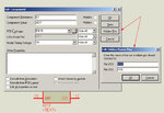
I try to connect the vdd and vss connection in 4017.but there is no pin of vdd n vss.i found out the hidden pin in properties and after edit it i tried run the software.it show the errors as "no power supply specified for the net 16 in the power rail configuration".What i should do?

thank you.
 

is "isisi" supposed to be Proteus ISIS?

If so then you don't need to connect them, they are hidden pins and already connected to the supply lines.

Snap1.jpg

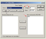
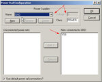
Is you open the menu, Design -> configure power lines you will see a dialog with the default supply lines

Snap2.jpg

Snap4.jpg

As you can see Vdd is set to 5v (same as Vcc) and Vss to 0 (gnd)
 
Capture.PNG

this is the circuit i tried to modified using phototransistor.But led at the output still not light up.what should i do??
thank you.
 

this is the zip file.

thank you.
 

Attachments

  • circuit.zip
    18.8 KB · Views: 106

Change the value of R5 to a higher value like 10k so that Q2 can turn on/off instead of permanently on like it is now

Restore the 4017 supplies to VDD and VSS and add a clock source because the 555 is not creating pules (I have no idea why) and it will work
 

i want look at your edited project file.can you sent to me that edited project file?
 

I don't have it so rather than doing myself the changes and provide you the circuit you should be able to do it yourself
 

What you mean by "restore the 4017 supplies to VDD and VSS"and how can i add a clock source and to the which pin i should connect??
 

The default settings for VDD and VSS are as shown in the first image in post #2 above, but you have changed that and connected VDD to net 16 (not 16v) and VSS to net 8 (not 8v). Restore them as they are by default or just delete the component and place a new one in the schematic.

In the left side icon menu (the vertical one) there is a button with a sinusoidal inside a circle, it has source generators, one of them is DCLOCK (digital clock) , use that for the 4017 clock pin
 

Capture.PNG
is that the circuit as shown in the above picture?
or i need to do any other changes?
cause its still not light up.
 

You still haven't corrected VDD and VSS of 4017

Disconnect the 555 and connect just the clock generator to the clock input, you can't drive one input from two outputs simultaneously
 

how can i modify it with two phototransistor and interface with PIC and display the output in the LCD?
any idea??
 

Status
Not open for further replies.

Similar threads

Part and Inventory Search

Welcome to EDABoard.com

Sponsor

Back
Top