demetal
Full Member level 5
- Joined
- May 2, 2011
- Messages
- 275
- Helped
- 21
- Reputation
- 42
- Reaction score
- 21
- Trophy points
- 1,298
- Location
- Kingdom Of Kochi
- Activity points
- 3,173
Follow along with the video below to see how to install our site as a web app on your home screen.
Note: This feature may not be available in some browsers.
Lets put it in a simple way.
AC signals have equal areas in negative and positive cycles. Duration of positive and negative cycles may be different.
If any signal doesn't satisfy the above, then its a combination of AC and DC.
Now i have got another doubt.... in digital communication do we use AC signal or DC signal...? also what type of Signal (AC or DC) will we get after the fourier transform or such transforms.... please help... it seems that my engineering skills are still poor....
In digital systems we don't see signals as AC and DC, we consider them as true/false, high/low or 1's/0's etc... These signals could be AC only (as amplitude modulation of a carrier), DC only (as the 0V-5V between CMOS logic ICs) and both AC-DC (as the RS232 signals +/- 12V for example).
In brief:
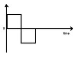
A signal that has a zero average value is said to be AC only.
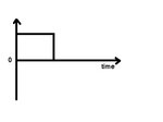
A signal that its amplitude doesn't change its sign is said to be DC only (constant or varying).
A signal that doesn't have a zero average value and its sign changes, is said to be a combination of AC and DC.
Kerim
No, it isn't. That criticism, could, however be applied to may of the answers we see on this forum.... this is a stupid question...
Think of the definition of d.c. and a.c.... but i am still confused about dc and ac... here are two wave forms... i want to know what type of (AC or DC) wave is it...
While it's true that a d.c. with ripple, for instance, can me shown to consist of the sum of a d.c. and an a.c., that's academic, and does nothing to help you.
No, internally, they are a series of AC circuits charging and discharging the capacitors such as transisor gates and routing metals and keeps changing the direction of the current. For example, look at what a clock does to the nets on clock tree.By digital communication, if you mean communication inside a wired digital system, its just DC. Any digital system is just a network of switches that switch on and off in a particular manner so as to do what ever function is required. But, any Dc signal switching that fast will not be a pure DC signal and will have plenty of transient components in it. If you look at the out put pin of even a simple and gate when it switches, with an oscilloscope, you'll not find an exactly clean transition there.
The output of fourier transform gives the frequency components of the wave on which its applied.
No, internally, they are a series of AC circuits charging and discharging the capacitors such as transisor gates and routing metals and keeps changing the direction of the current. For example, look at what a clock does to the nets on clock tree.
No, internally, they are a series of AC circuits charging and discharging the capacitors such as transisor gates and routing metals and keeps changing the direction of the current. For example, look at what a clock does to the nets on clock tree.