Welcome to our site! EDAboard.com is an international Electronics Discussion Forum focused on EDA software, circuits, schematics, books, theory, papers, asic, pld, 8051, DSP, Network, RF, Analog Design, PCB, Service Manuals... and a whole lot more! To participate you need to register. Registration is free. Click here to register now.
Hi all.
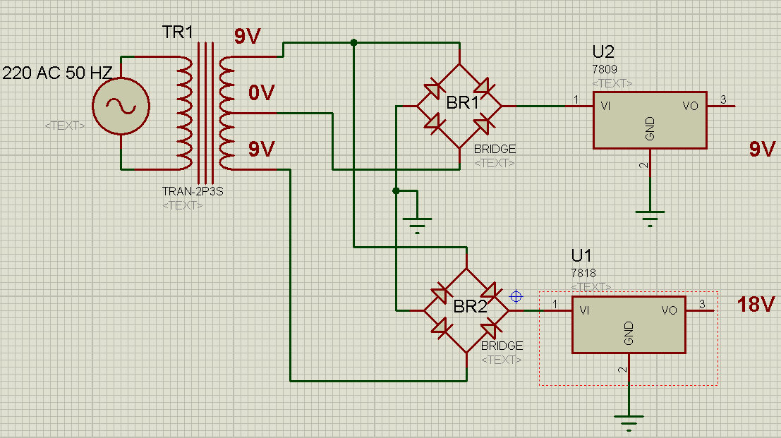
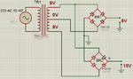
I want to generate 2 positive voltages from one center tapped transformer, I want to make sure that this configuration is ok, what is your opinions??
thanks alexan_e for ur reply.
Now how can i solve this problem??
I mean how can i get the two DC e using this transformer??
I am planning to use regulators, so i don't want to use the 18V as an input to the 9V regulator
---------- Post added at 21:42 ---------- Previous post was at 21:32 ----------
Normally you ground the center tap and you connect the two ends to a bridge to get about +12.5/-12.5 DC.
If you don't use the gnd in the center tap but you connect the output "negative" voltage to the gnd after the bridge then you can get 25v.
The problem is that you want to use two different grounds together and I think it will not work.
You right side schematic with one bridge will work, I'm not sure about the left side with two bridges.
Actually your link schematic in post #3 works fine because of the diodes that are connected to the gnd side of the 12v regulator.
The only problem is that 7812 needs 14v input and with 9v AC (about 12.5v DC) you will have less so the regulator will not work correctly
The circuit in post #1 will work but it is inefficient.
I'm using a simulator. I attach capacitors and loads to the 9V and 18V points.
It will be okay with the 18V. Voltage rises to 24V with light load.
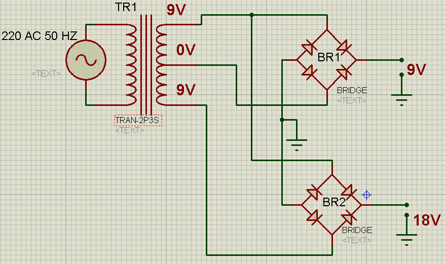
And the 9V supply will rise to 24V max as well. Notice that the common ground is connected to the bottom left diode in the 18V diode bridge. When that diode turns on it pulls the common ground into the negative.
Post #3 left hand circuit is based on post #1. The regulator will produce 9V however there will be an offbeat circuit path through a diode or two. Not the most efficient.
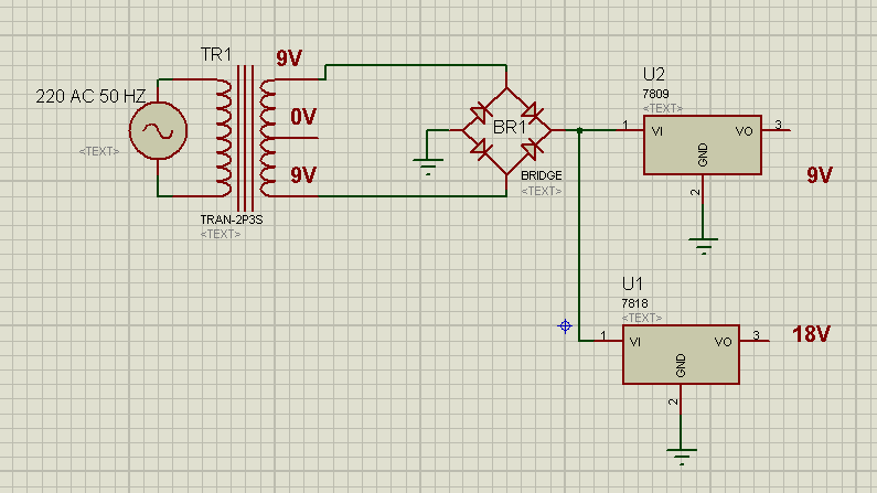
Post #3 right hand circuit will work. It is straightforward. Only slightly more efficient than the left hand circuit.
However it wastes half the power through heat.
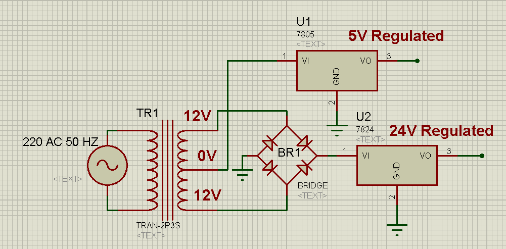
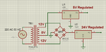
I can confirm alexan's statement post #10. The dual supply layout in post #7 can work. It will also give what post #1 asks regarding the 9-0-9 dual supply.
The center tap is at zero. The center tap is the positive end of a 9V full-wave center tap supply. The load is at -12 VDC. (Assuming capacitor filtering and light load.)
Its diodes perform double duty. Because they also power the 18V full-wave bridge supply. The load will get -12 DC and +12 DC at the ends (assuming capacitor filtering and light load). Normal and stable readings.
Common ground is the lowest node of the diode bridge. We make common ground our reference zero V.
Then the center tap is +12 (relative to common ground). High node of diode bridge is +24.
The center tap can feed pin 1 of a regulator. Regulator pin 2 can go to common ground.
There are no direct shorts at any point in the cycle.
In fact, the circuit from post #10 is the only one that's working as shown, all others are at least missing capacitors. Is it so difficult to draw the schematics completely?
Circuit #10, is basically a modfied standard center tapped transformer dual supply circuit. If most of the power goes to the lower output voltage and only a small amount to the other, the transformer efficiency can be increased by using a bridge rectifier for the low voltage and a doubler circuit for the high voltage.
This site uses cookies to help personalise content, tailor your experience and to keep you logged in if you register.
By continuing to use this site, you are consenting to our use of cookies.