Continue to Site

Welcome to EDAboard.com

Welcome to our site! EDAboard.com is an international Electronics Discussion Forum focused on EDA software, circuits, schematics, books, theory, papers, asic, pld, 8051, DSP, Network, RF, Analog Design, PCB, Service Manuals... and a whole lot more! To participate you need to register. Registration is free. Click here to register now.

[SOLVED] Is there any limitation in fan-in of CMOS buffer

Status
Not open for further replies.

Prakash12345

Junior Member level 2
Joined
Jun 22, 2016
Messages
21
Helped
0
Reputation
0
Reaction score
0
Trophy points
1
Activity points
185
How to increase fanout of CMOS buffer

Hi,
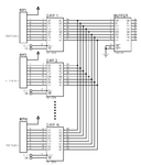
I'm new to online forum. I want to interface 74HC541(Buffer) to 74HC574(D-f/f). The thing is 100's of D-f/f parallel interface as shown in figure(Fig.1).
Input and load capacitance limits it to 10 to 15 fanout. Fanout of buffer current wants to charge input capacitance of D-f/f. So increasing D-f/f increases charge time of input capacitance.
My question is this can be overcome by giving more current to increase charge current to input capacitance by adding pullup resistor to input of D-f/f(Fig.2) or BJT emitter follower(Fig.3).
This would correct or not. fanout.jpg
 

Re: How to increase fanout of CMOS buffer

CMOS IO standard has no fixed fan-out limit. Everything depends on required speed. You should also consider wiring/PCB capacitance, it is possibly higher than logic input capacitance. I also presume that "100's" of paralleled interfaces involve a considerable wire length and you need to think about distributed buffers.

Your suggested solutions are just useless or even making signal quality worse. If necessary use multiple cascaded bus buffers, e.g. HC541.
 
How many inputs can be connected to input pin of 74HC541(Buffer). Whether it related to current or voltage or capacitance or timing. Please give me fan-in calculation of CMOS-CMOS interface.
 

Hi,

Input to input?

It makes no sense. An input is a load. And a load needs a driver. And the driver needs to "drive" the load.
But you have no driver = output in your question.

Klaus
 
OK, then how many CMOS IC outputs can given to input pins in a buffer?
 

Only one signal output should be connected to an input. If you connect more than one signal output to an input then the outputs are shorting each other and the resulting signal combination will not have valid logic levels.

A Cmos input has a very high impedance (almost no current) so many can be connected to a Cmos output (driver) until the resulting capacitance slows down the driver.
 

Hi,

It seems you didn´t understand:

output = driver, source (e.g. locomotive)
input = load (e.g. a wagon)

Your first question was: how many wagons can I connect together? (without locomotive)
Now you ask: How many locomotives can I connect to a single wagon?

The question must be: How many wagons can a single locomotive pull?

--> How many inputs can I an single output drive?

Now you have to define:
What is the "input"?
What is the "output"?
(Wich of them is the HC541?)

Answer: count = Fan_Out / Fan_in

Klaus
 
Last edited:

Re: How to increase fanout of CMOS buffer

Your emitter follower is almost useless. Do it like this which is frequently used to drive a Mosfet that has a high input capacitance:
 

Attachments

  • emitter follower.png
    emitter follower.png
    16.6 KB · Views: 112

Here is the circuit. Input is 74HC541(Buffer) and output is 74HC574(D-F/F). What modification I have to do to fill my requirements? I want to interface minimum 64 D-F/F to my circuitsBuffer.png
 

Here is the circuit. Input is 74HC541(Buffer) and output is 74HC574(D-F/F). What modification I have to do to fill my requirements? I want to interface minimum 64 D-F/F to my circuitsView attachment 130035

Why don't you just say you are trying to MULTIPLEX N D-FFs onto one bus.
 

You didn't yet mention parallel connection of multiple tri-stated outputs. The question has noting to do with "fan-in", problem is still fanout of the output drivers.

If you don't want to parallel-connect 64 outputs, you can e.g. form groups of 8 in the first level and use additional tri-state drivers. It's enable signals need additional logic.
 

You need to have an N-wide decoder (e.g. for 8 D-FFs a 3-to-8 decoder) and connect that to the OE pins of each D-FF. You don't actually need the HC541 as the 8-bit D-FFs already have tri-state enables.

- - - Updated - - -

This also begs the question why are you building this circuit with SSI components a somewhat inexpensive < $20 FPGA would have 150+ I/O and could do this without a problem on significantly less real estate and would use far less power if you need to drive some big load at the final output you can then add that one HC541 to the final output.
 
Thanks a lot and I found solution at last post. I'm new to online forum and I have to improve question asking skills.
 

Status
Not open for further replies.

Part and Inventory Search

Welcome to EDABoard.com

Sponsor

Back
Top