DZC
Full Member level 2
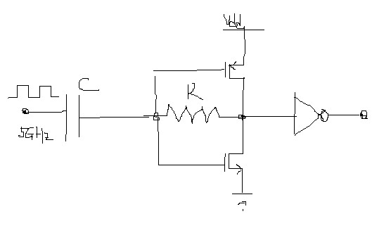
To correct the duty cycle of a 5GHz clock, I come up with the attached circuit.
For 5GHz clock, R=10K and C=100fF.
It works almost perfect according to simulation. But I just kind of worried, is there any issue associate with this scheme I have ignored?
For 5GHz clock, R=10K and C=100fF.
It works almost perfect according to simulation. But I just kind of worried, is there any issue associate with this scheme I have ignored?