Continue to Site

Welcome to EDAboard.com

Welcome to our site! EDAboard.com is an international Electronics Discussion Forum focused on EDA software, circuits, schematics, books, theory, papers, asic, pld, 8051, DSP, Network, RF, Analog Design, PCB, Service Manuals... and a whole lot more! To participate you need to register. Registration is free. Click here to register now.

Is my RF filtering effective enough?

Status
Not open for further replies.

neazoi

Advanced Member level 6
Joined
Jan 5, 2008
Messages
4,119
Helped
13
Reputation
26
Reaction score
15
Trophy points
1,318
Location
Greece
Activity points
36,918
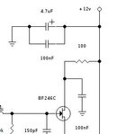
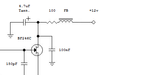
Hi, I have an oscillator and I would like to know if the way I did the rf filtering (with the bypass capacitors and the tantalum electrolytic), is effective enough. I consider 1-30MHz as the operation of the oscillator, are the values of the capacitors ok?
 

Attachments

  • capture24380.jpg
    capture24380.jpg
    7.7 KB · Views: 96

The main filtering there is the 100nF from the drain of the fet, Personally I would add a ferrite bead in series with the 12V rail, or maybe a few tens of ohms of series R?

The tant is useful mainly because it is predominantly resistive at HF (They are notoriously poor RF caps), which helps to damp any resonances in the supply wiring.

I assume the thing is Colpitts or some sort of Hartley design, with the output taken from the source?

Regards, Dan.
 
  • Like
Reactions: neazoi

    neazoi

    Points: 2
    Helpful Answer Positive Rating
The main filtering there is the 100nF from the drain of the fet, Personally I would add a ferrite bead in series with the 12V rail, or maybe a few tens of ohms of series R?

The tant is useful mainly because it is predominantly resistive at HF (They are notoriously poor RF caps), which helps to damp any resonances in the supply wiring.

I assume the thing is Colpitts or some sort of Hartley design, with the output taken from the source?

Regards, Dan.

The output is taken from the gate through a crystal or a coil (both work).

About the bead, you mean adding to the 12v directly or after the tantalum and before the 100R?

So in general, this topology and the values I have chosen (100nf) form an effective decoupling for HF?
 

Also, do I need the decoupling cap at the tantalum?
 

The parallel capacitors do little at the moment because they are shunted by the impdedance of the power lines. As Dan points out, the real filtering is done by the RC network of 100R and the 100nF capacitor at the drain pin of the FET. It would make more sense to move the tantalum so it is across the other 100nf capacitor, that shouldn't change the operation of the circuit but the longer RC time constant will help to filter out lower frequency interference from the supply.

In general, always connect a ceramic capacitor across a tantalum type (or any other electrolytic) in RF situations. A good ceramic capacitor has low ESR at high frequencies while electrolytics get higher as the frequency increases. Use an electrolytic to achieve the value you need and a ceramic across it to keep it filtering at HF.

Brian.
 
  • Like
Reactions: neazoi

    neazoi

    Points: 2
    Helpful Answer Positive Rating
The parallel capacitors do little at the moment because they are shunted by the impdedance of the power lines. As Dan points out, the real filtering is done by the RC network of 100R and the 100nF capacitor at the drain pin of the FET. It would make more sense to move the tantalum so it is across the other 100nf capacitor, that shouldn't change the operation of the circuit but the longer RC time constant will help to filter out lower frequency interference from the supply.

In general, always connect a ceramic capacitor across a tantalum type (or any other electrolytic) in RF situations. A good ceramic capacitor has low ESR at high frequencies while electrolytics get higher as the frequency increases. Use an electrolytic to achieve the value you need and a ceramic across it to keep it filtering at HF.

Brian.

Thank you, I will move the tantalum as you suggested and remove the 100nf at the supply rails.
Do you think that it will be a good Idea to add a ferite bead at the rails?
 

The ferrite bead may help but the effect may not be dramatic. If you need better RF isolation a choke would be better. The real issue with the supply rails is that they inevitably go to all parts of the circuit and are therefore an easy path for interference to travel along from one stage to another. The physical location of the power wiring will to a large extent decide how much signal is coupled along it. For example, if your oscillator is inside a screened box and interference can enter the box along the supply wire it will work like an antenna, introducing noise and allowing oscillation out as well. In a case like that you need two stages of filtering, one as mentioned in the earlier post and another as the power enters the screened area.

Brian.


I wonder about the value of the choke, if it is effective or not. Beads are relatively broadband (I think?).
The oscillator is followed by some amplifier. I am thinking of using the same decoupling scheme for each of these stages. The whole circuit will be placed inside a aluminum case and a 10nF feedthrough capacitor will connect the PSU to it.

I worry especially for the inter-stage interference, that is why I thought it would be better to use the same decoupling scheme for each of these stages.

How do you think of that scheme?

- - - Updated - - -

Ok here it is, based on the info in this thread.
I hope it is ok for HF.
 

Attachments

  • Untitled.png
    Untitled.png
    7.3 KB · Views: 101

RF beads vary with core type and frequency and impedance , thus 100 may be enough or bead may add up to 500 ohms more or less.\But cap may not be low ESR/ESL at f so RF cap is used in // (parallel) like 0.01uF or less with rising f ( eg 47pF @ 1GHz) preferably NPO which have lowest ESR or film or Murata type RF caps but depends on tant. ESL or SRF
 
  • Like
Reactions: neazoi

    neazoi

    Points: 2
    Helpful Answer Positive Rating
Beads with a wire through them are no more broadband than any other inductor. The idea of it being a choke is that XL is high at the frequency you are trying to block. Increasing the inductance by using ferrite does increase XL but the effect may be small in your application.

I would go with the same RC filter at each stage, as long as the current is low enough that a reasonable value of R can be used without causing too much voltage drop. Additionally, add a ceramic capacitor across the incoming power rail at the point where it physically enters the circuit. That should help to minimize the coupling along the supply line as well as isolate the individual stages.

Brian.
 
  • Like
Reactions: neazoi

    neazoi

    Points: 2
    Helpful Answer Positive Rating
I would go with the same RC filter at each stage, as long as the current is low enough that a reasonable value of R can be used without causing too much voltage drop. Additionally, add a ceramic capacitor across the incoming power rail at the point where it physically enters the circuit. That should help to minimize the coupling along the supply line as well as isolate the individual stages.
Brian.

Ok so if I understood well, I shall remove the bead and replace it with a shunt capacitor to the GND at that point, say 100nF? (oscillator frequency 0.5-30MHz)
 
Last edited:

Yes, that is correct. You can still leave the ferrite bead there if you want to, it does no harm and may be beneficial but it's effect would be very small compared to adding the extra capacitor.

Your original schematic has gone full circle - except for the tantalum moving across the other capacitor!

Brian.
 
  • Like
Reactions: neazoi

    neazoi

    Points: 2
    Helpful Answer Positive Rating
Yes, that is correct. You can still leave the ferrite bead there if you want to, it does no harm and may be beneficial but it's effect would be very small compared to adding the extra capacitor.
Brian.
Thank you!
The bead should be connected directly to the vcc or after the first 100nF shunt?

I also wonder if 100uF instead of 4.7uF should be better used.
 

It would probably be better placed on the incoming supply before the first capacitor as long as it is physically close to the capacitor and not further along the wiring. It would turn the circuit into an LC-RC filter giving more rejection of power line RF.

The electrolytic capacitor will do almost nothing at frequencies higher than a few hundred KHz, it's job is primarily to reject LF from the supply and maybe increase stability of the amplifier stage if it's prone to LF oscillation. If you increase the value it will give better supply noise rejection but at the expense of making the oscillator slower to start up because of the RC time constant with the 100R resistor. If the supply is stable it should be fine with 4.7uF.

Brian.
 
  • Like
Reactions: neazoi

    neazoi

    Points: 2
    Helpful Answer Positive Rating
It would probably be better placed on the incoming supply before the first capacitor as long as it is physically close to the capacitor and not further along the wiring. It would turn the circuit into an LC-RC filter giving more rejection of power line RF.

The electrolytic capacitor will do almost nothing at frequencies higher than a few hundred KHz, it's job is primarily to reject LF from the supply and maybe increase stability of the amplifier stage if it's prone to LF oscillation. If you increase the value it will give better supply noise rejection but at the expense of making the oscillator slower to start up because of the RC time constant with the 100R resistor. If the supply is stable it should be fine with 4.7uF.

Brian.

Do you think it would be beneficial for ultimate isolation, to have a separate transistor regulator (https://www.bristolwatch.com/ele/img/zr4.gif) for each stage? (oscillator and amplifiers)
Or is it too much?
 

I would only use a regulator like that (which isn't very efficient anyway) if there was a chance of severe voltage fluctuations on the supply. I think I would use a 78Lxx regulator anyway as it gives vastly superior performance over a Zener and current amplifier. For blocking RF it would serve no useful purpose at all. So the short answer is if your supply is already regulated, don't do it!

Brian.
 
  • Like
Reactions: neazoi

    neazoi

    Points: 2
    Helpful Answer Positive Rating
Status
Not open for further replies.

Similar threads

Part and Inventory Search

Welcome to EDABoard.com

Sponsor

Back
Top