muffassir
Member level 3
- Joined
- Sep 15, 2011
- Messages
- 67
- Helped
- 10
- Reputation
- 20
- Reaction score
- 10
- Trophy points
- 1,288
- Location
- Planet Earth
- Activity points
- 1,802
Hi ,
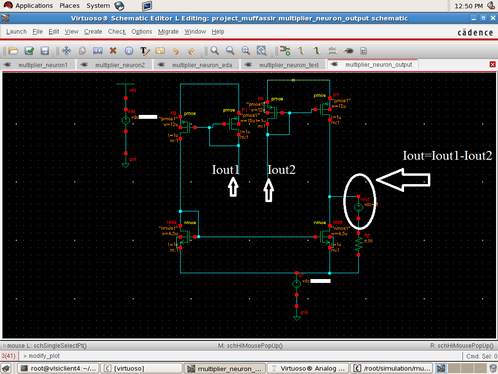
In my circuit i have output currents as Iout1 and Iout2 from two places.What i want is Iout=Iout1-Iout2.
This is my circuit for this.I urge you all to correct the circuit if it is wrong .I have used current mirrors as shown in the image.
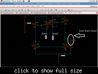
will this ckt will give me the desired output.
In my circuit i have output currents as Iout1 and Iout2 from two places.What i want is Iout=Iout1-Iout2.
This is my circuit for this.I urge you all to correct the circuit if it is wrong .I have used current mirrors as shown in the image.
will this ckt will give me the desired output.