Continue to Site

Welcome to EDAboard.com

Welcome to our site! EDAboard.com is an international Electronics Discussion Forum focused on EDA software, circuits, schematics, books, theory, papers, asic, pld, 8051, DSP, Network, RF, Analog Design, PCB, Service Manuals... and a whole lot more! To participate you need to register. Registration is free. Click here to register now.

[SOLVED] Is it possible to interface a MMC to PIC16F877A?

Status
Not open for further replies.

vinodstanur

Advanced Member level 3
Joined
Oct 31, 2009
Messages
751
Helped
114
Reputation
234
Reaction score
114
Trophy points
1,333
Location
Kerala (INDIA)
Activity points
7,054
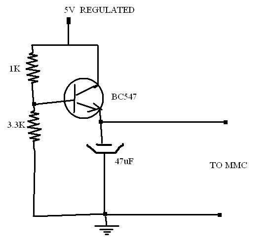
I heard that an MMC card could be accessed by a microcontroller via SPI mode. But it says a memory card is read or write is done by 512 bytes at a time. If it is so, then the PIC16F877A doesnt have that much RAM to store this 512 bytes. But now i got some information that MMC could also be accessed by 64bytes read or write at a time. if this is possible then i think it could be accessed by a PIC16F877A. Any one know about this then pls help me.
 

SD / MMC card are SPI interfaced , it should not be a problem in interfacing it....

check this
**broken link removed**
yes i checked that link and got some idea...There after, i collected some more information about the mmc initialization via spi.
Those information is given below:
MMC Initialization
1. Set chip select pin
2. Clear chip select pin
3. Pass 0xff, 0x40(for initialize), 0x00 (4 times- for reset), 0x95 (check error sum) to the MMC card
4. Read from MMC.
5. Check receive data is equal to 0x01
6. If received data is not equal to 0x01 then repeat step 6 up to 1000 times.
7. If 0x01 not received go to step 15.
8. Set chip select pin
9. Clear chip select pin
10. Pass 0xff, 0x50(for block select), 0x00 (2 times- for reset), 0x 02, 0x00(block length,512) 0xff (check error sum) to the MMC card
11. Read from MMC.
12. Check receive data is equal to 0x01
13. If received data is not equal to 0x01 go to step 15
14. If 0x01 received send a message to LCD
15. Set chip select pin
16. If card not initialized send a message to the LCD or send data through USART

MMC Data Write
1. Clear chip select pin
2. Pass 0xff and 0x58 (for write) to the MMC card
3. Write location number to the MMC card
4. Read from MMC.
5. Check receive data is not equal to 0x05 then repeat step 4 up to 100 times.
6. Before 1000 times the 0x05 is received go to step 8
7. If received data is equal to 0x00 send a error message
8. Set chip select pin
9. Write data to the MMC card
10. After 512 data writes, select the location number (location number+512) and go to step 1.
MMC Data Read
1. Clear chip select pin
2. Pass 0xff and 0x51 (for read) to the MMC card
3. Write location number to the MMC card
4. Read from MMC.
5. Check receive data is equal to 0x00 then repeat step 4 up to 1000 times.
6. After 1000 times go to step 8
7. If received data is equal to 0x00 send a error message
8. Set chip select pin
9. Read data from MMC card
10. Send these data to the computer through USART
11. After 512 data writes, select the location number (location number+512) and go to step 1.


There after, i wrote a program (below)


Code:
#include<pic.h>
#define _XTAL_FREQ 20e6
#define CS RC2

unsigned char t,rec,dat,tempbuf,readdata;
unsigned int count;
void usrt_init()
	{

	TRISC6=0;
	TXSTA=0b00100110;
	RCSTA=0b11010000;
	SPBRG=10;
	}
void string(const char *p)
	{
	while(*p)
		{
		TXREG=*p;
		while(TRMT==0);
		p++;
		}
	}
void spi_init()
{
TRISC4=1;
RC2=0;RC3=0;RC5=0;
TRISC2=TRISC3=TRISC5=0;

SSPCON=0b00100000;
SSPEN=1;
SMP=1;
CKE=0;
CKP=1;
}
////////////////////////////////////////////////////
 void spi_write()
 {
  SSPBUF=dat;
 while(BF==0);
  tempbuf=SSPBUF;
 }
 
////////////////////////////////////////////////////
 void spi_read()
 {
  SSPBUF=0xff;
 	while(BF==0);
  readdata=SSPBUF;

 }
////////////////////////////////////////////////////
////////////////////////////////////////////////////
void mmc_init()
{	
	CS=1;
	CS=0;

	dat=0xff;
	spi_write();
	dat=0x40;
	spi_write();
	dat=0x00;
	spi_write();
	dat=0x00;
	spi_write();
	dat=0x00;
	spi_write();
	dat=0x00;
	spi_write();
	dat=0x95;
	spi_write();
	spi_read();
	count=0;
	while((count<1000)&&(readdata!=0x01))
	{
	spi_read();
	count++;
	}
	if(count>=1000)
	{
	string("FIRST ERROR");
	}
	
   else
   {
	CS=1;
	CS=0;
	dat=0xff;
	spi_write();
	dat=0x50;
	spi_write();
	dat=0x00;
	spi_write();
	dat=0x00;
	spi_write();
	dat=0x02;
	spi_write();
	dat=0x00;
	spi_write();
	dat=0xff;
	spi_write();
	spi_read();
	count=0;
	while((count<1000)&&(readdata!=0x01))
	{
	spi_read();
	count++;
	}
	if(count>=1000)
	{
	string("SECOND ERROR");
	while(1);
	}
	
	{
	CS=0;
  	string("INITIALIZATION COMPLETE  ");
	}
	}
}

main()
{
TRISD=0;
PORTD=0;
usrt_init();usrt_init();
spi_init();__delay_ms(10);
mmc_init();
while(1)
	{
	CS=0;
	dat=0xff;
	spi_write();
	dat=0x58;
	spi_write();
	dat=0x01;
	spi_write();
	d:spi_read();
	if(readdata==0x05){string("data write mode activated   ");while(1);}
	else {string("trying    ");goto d;}	
	}
}


Now i am getting "SECOND ERROR".

Since i am not getting "FIRST ERROR" i think my connections are right.
What should i do?
 
Last edited:
Hello,

Matrix Multimedia do a FAT and FAT32 driver inside the Flowcode software. This supports PIC, dsPIC, AVR and ARMSAM7S chips. I wrote the component and can provide help if needed.
 

Hello,

Matrix Multimedia do a FAT and FAT32 driver inside the Flowcode software. This supports PIC, dsPIC, AVR and ARMSAM7S chips. I wrote the component and can provide help if needed.

But before going to file system , i want to write some data to MMC and and want to read it back. Now i have initialization error. I am getting first response as 0x01. That was correct. Then after that ,i am not getting readdata as 0x01 and got second error.
But if i allow the it to continue after the second error (by deleting the while(1) after second error) then I am getting the required readdata 0x05!!! This means the write mode activated.. But i cant write and read back data. Getting blank readdata for 512 blocks...... My problem is that "SECOND ERROR". So any one could help me?
 

Just post the link where it is mentioned read and write could be done in 64 Byte blocks..

The MMC/SD Card needs to have 512 byte buffer, you can use a 16F877A with a buffer memory. Another option is to use a pin compatible device like the 18F4620.
 

it may be wrong information(i got that info from one friend)..okay...leave it...Now, how it read the 512 bytes? I think it is similar to ordinary read operation (sending 0xff and reading the response for each byte until it reaches 512. Is it right or wrong? I am new to this...and i searched a lot in net about initialization of MMC or SD via SPI mode. Then the results are limited and what i could see is CMD0 CMD1 etc....But am not getting what is CMD0 CMD1:?: ets etc..........
 

you should download a copy of the MMC specs first, all the commands required to access the card are given there. The specs also contain the initialisation procedure, ie: which command to send first etc.

Without Initialisation the device cannot work, so you have to solve this problem first.

What device & compiler are you using ??

Lets consider some scenarios....

1. Using a buffer memory

To read data from the card, you need to read 512 bytes of data, but you can stop in between (say at 64 bytes), but to write data you need to write 512 bytes of data. This can be done easily if the data is stored in a buffer memory like a FLASH RAM (or FRAM), you simply have to read the FRAM and then transfer the data directly to the card byte by byte.

2. Without buffer memory

The 16F877A by itself does not have sufficient memory, so there is a limit to how much data can be stored in the RAM (say 20 bytes). These 20 bytes of data could be written to the card, but then the remaining 492 bytes of data will have to be null. This means existing data in the card gets erased. You could avoid this problem by reading in the data first into the PICs RAM, but with limited RAM size you cannot read in all the data, so editing a MMC card using a 16F877A cannot be done.

thanks
a
 

Download MikroC manual if you are using this compiler. Every thing is given in it.

Here is a part of manual.
 

2. Without buffer memory

The 16F877A by itself does not have sufficient memory, so there is a limit to how much data can be stored in the RAM (say 20 bytes). These 20 bytes of data could be written to the card, but then the remaining 492 bytes of data will have to be null. This means existing data in the card gets erased. You could avoid this problem by reading in the data first into the PICs RAM, but with limited RAM size you cannot read in all the data, so editing a MMC card using a 16F877A cannot be done.

thanks
a


If i am writing simply a letter say 'A' to all 512 bytes using a loop just for testing, then i think i could fill 512 bytes in MMC with 'A' .right?:?:

And in reading case if i don't want to store the data in RAM , and if i would like to stream the data read data from the MMC byte by byte through USRT, then i think in my case, i could use PIC16F877A atleast for study purpose . Right?:?:


you should download a copy of the MMC specs first, all the commands required to access the card are given there. The specs also contain the initialisation procedure, ie: which command to send first etc.
So from where i could get those required data? I searched in google a lot but i couldn't find the exact initialization steps other than some CMD0,CMD1 etc etc......
 
Last edited:

So from where i could get those required data?
Because official MMCA documents are available to members only, you may want to download a manufacturers product documentation from the internet, e.g. https://elinux.org/images/d/d3/Mmc_spec.pdf The SanDisk Manuals have been available from Sandisk directly, but apparently they are not longer trying to serve their customers.

To add another comment to the PIC16 and required RAM for MMC topic: You'll mostly want to buffer sectors in two situations:
- when updating (read/modify/write) data sectors
- when working with FAT structures, including write operations to it
 

If i am writing simply a letter say 'A' to all 512 bytes using a loop just for testing, then i think i could fill 512 bytes in MMC with 'A' .right?

And in reading case if i don't want to store the data in RAM , and if i would like to stream the data read data from the MMC byte by byte through USRT, then i think in my case, i could use PIC16F877A atleast for study purpose . Right?

Yes.

The initialisation sequence will be in the specs, download the file posted by Fvm, it should be possible to get a condensed version of the SDCard specs, search in google.
 

yes i downloaded Sandisk spec. Now i am confused...I am having MMC and not SD. Every document is related to SD. Then i think there will be some difference in initialization of both....But i dont know what is my problem. I am getting idle bit as 1 after reading the response for CMD0. Then i am not getting response 0x00 for CMD1. But when i slip CMD0 and then i set block size using command(0x50,0,512,0xff) but i am not getting response 1. Then i continued. I got response 0x05 for command(0x58,0,512,0xff) which is correct!!!! When i slip the set block size command(0x50,0,512,0xff) then i cant get reply 0x05. Now dont know what is my exact problem.
I set spi clock as f/64 ie 20000khz/64 =312.5 which is below 400khz....
 
Last edited:

both specs are different. Decide on which card you want to use MMC or SDCard.

How is the voltage translation from 5 to 3.3 V done ? Please post the schematic
 

both specs are different. Decide on which card you want to use MMC or SDCard.
Yes. Most drivers are however designed to support both types, because the differences are small. If you support both types, you'll identify the present card type in one place of the initialization dialog.
 

both specs are different. Decide on which card you want to use MMC or SDCard.

How is the voltage translation from 5 to 3.3 V done ? Please post the schematic


The above is my power supply circuit. At present i don't have other regulator ICs with me. So i did the above circuit. I measured the voltage and it was about 3.3 volt. But i didn't tested the voltage at current 100mA.:wink:
 

but now i connected a 4.2v zener diode instead of 3.3 K and replaced 1k with 560E resistor. Then replaced BC547 with a power transistor. But still the same problem. Could any one give me the correct initialization steps ?
 

The 47 microF capacitor would slow the pulses down.

To start with use a simple resistor divider to bring down the voltage to 3.3 V, I know this is not a good design, but it works very well. Later after you have perfected the system, you could use transistors.

The datasheet indicates that an I/O port with TTL buffer has an Input High Voltage of 2 V to 5.5 V. Which means any voltage above 2 V would be a high state and anything lower would be low state. So just select a port that has a TTL buffer.

Connect this port directly to the Data Out pin of the MMC.
 

The 47 microF capacitor would slow the pulses down.
To start with use a simple resistor divider to bring down the voltage to 3.3 V
There's possibly a misunderstanding about voltage translation. The transistor cicrcuit is good for the 3.3V power supply. But the 3 logic signals from µP to MMC also need voltage translation. Here a simple resistive divider (e.g. 2.2k:3.3k) will work at lower speeds. As far as I see, it should be at least sufficient for the speed achieved by a PIC16 without using hardware SPI.
 

Yes the circuit which i had provided above is the power supply circuit only...and not the circuit for voltage translation for SPI pins.
Yes i used only a voltage divider for the level conversion. (MOSI,CS,SCK) and i directly connected the MISO since it is data out of MMC card. I didnt connected any capacitor in parallel to signals...

---------- Post added at 13:38 ---------- Previous post was at 13:35 ----------

And also my MMC is close to PIC. Wire length < 4cm
 

Status
Not open for further replies.

Similar threads

Part and Inventory Search

Welcome to EDABoard.com

Sponsor

Back
Top