Continue to Site

Welcome to EDAboard.com

Welcome to our site! EDAboard.com is an international Electronics Discussion Forum focused on EDA software, circuits, schematics, books, theory, papers, asic, pld, 8051, DSP, Network, RF, Analog Design, PCB, Service Manuals... and a whole lot more! To participate you need to register. Registration is free. Click here to register now.

ir2110- problem with connecting it to TI's microcontroller

Status
Not open for further replies.

vered&alon

Newbie level 3
Joined
May 5, 2010
Messages
4
Helped
0
Reputation
0
Reaction score
0
Trophy points
1,281
Activity points
1,318
hey all,

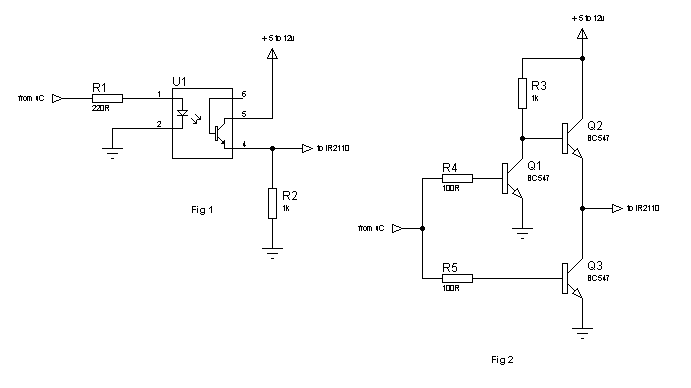
we have ir2110 gate driver with two power mosfets as it's switches.
the gate driver is connected to a TI microcontroller, who has logic '1'=3.3v.
as you can see in the datasheet attached, the gate driver expects Vih to get at least 9.5v, but the micrcontroller doesn't get that high.
does someone have an idea how we can solve this problem?

we really appriciate your help,
Alon & Vered.
 

Attachments

  • datasheet.pdf
    217.9 KB · Views: 141

Refer to Figure 12B for the full story. The point is, that IR2110 has separate logic (VDD) and output (VCC) supply. To drive the IR2110 with 3.3 V CMOS logic level, you have to supply VDD with 3.3V.

But. IR2110 logic delay may be inacceptable high at 3.3V supply, as indicated by figure 7C and 8C. This will be a problem a least for high switching frequencies, because precise dead time control becomes difficult. I would suggest a minimal VDD of 5V and 3.3V to 5V level translation for reliable operation.
 

Hi, at what frequency are you operating your Fet driver? If you are operating withing the range of khz,then you Vdd should be 5v-3.3v minimum but if are using low freq then your Vdd should be 12v.
 

I used IR2110 for my inverter project i use 50Hz as my frequency and apply 3.3v at pin 9 which is the Vdd pin, their is no output, i cheak the datasheet i found that Vdd pin is connected to Vcc pin,the i connect the Vdd pin back to my Vcc supply and everthing works fine,and when i start my pure sine wave inverter,i repeat the same thing, i now find out that even with 5v at pin 9 the Vdd pin, their is output at pin 1 and pin 7 of the IR2110 and i can say the diffrence their is the frequency because my carrier frequency is 15Khz.

---------- Post added at 14:11 ---------- Previous post was at 14:02 ----------

Many sinewave power inverters that uses IR2110 as fet driver uses minimum of 3.3v as their Vdd supply,but normal square wave used 12v for Vdd pin,

---------- Post added at 14:15 ---------- Previous post was at 14:11 ----------

@t vered you can't get more than 5volt from your microcontroler and if you connect your fet driver fine it should work with 5v.
 
Last edited:

i cheak the datasheet i found that Vdd pin is connected to Vcc pin
No it isn't. You mean, it's connected to the same supply in some of the example circuits.

As said, IR2110 can work at 3.3V VDD, while VCC must be above the undervoltage lockout threshold to get any output.
 

Yes, that's right Vcc must be above undervoltage lockout and Vdd from 3.3v but it does'nt work with low freq why?
 

If I remember right, it worked with low frequency, too. Low frequency may need larger bootstrap capacitor values, but the problem doesn't depend on VDD.
 

Hi,

I think I understood what kabiru meant. You may have seen in most square wave circuits that Vdd is connected to Vcc and applied the same voltage (12v), however, in the high-frequency circuits, Vdd is NOT connected to Vcc and given an independent 3.3-5v supply.

The reason is, usually in square wave inverters, the IR2110 is driven by a PWM chip, eg SG3525 or TL494 or even simply an astable multivibrator, eg 4047. These can nicely work with 12v and the output is near about 12v level, so IR2110 needs no separate Vdd power and can be run from the same Vcc voltage.

In high-frequency inverters, I think you saw it in sine wave inverters, microcontroller is used for SPWM. Here IR2110 can not be run from the same 12v as the input (output from microcontroller) will have a peak of 4.5-5v (for 5v microcontrollers) or 3-3.3v (for 3.3v microcontrollers). That's why the separate 3.3/5v is applied.

It should work with 3.3v but not very reliable. So, you should not go below 4-5v. A good solution, as suggested by FvM, is to use a 3.3v to 5v (or even 12v) interface and use the 5v (or 12v) level for the IR2110.

Hope this helps.
Tahmid.

---------- Post added at 21:20 ---------- Previous post was at 21:08 ----------

Hi,
Here are two circuits for interfacing(to shift to 5v or 12v level):

26_1293981642.png


Fig 1. can be used for low frequency.
For high frequency Fig. 2 can be used but the output is inverted, so you must take that in mind.
There are many more solutions, these are just 2.

Hope this helps.
Tahmid.
 
  • Like
Reactions: FvM

    FvM

    Points: 2
    Helpful Answer Positive Rating
I basically agree. There's an unclear point about IR2110 possibly not working at 3.3V and low frequency, but I don't see why.

For 3.3V to 5V level conversion, I used 74HCT logic.
 
  • Like
Reactions: Tahmid

    Tahmid

    Points: 2
    Helpful Answer Positive Rating
Hi,the supply for the Vdd is not coming out of the microprocessor or pic, a simple regulator is used eg 7805 from the Vcc supply to regulate the voltage from 12v to 5v with two diode connected in series,this diode drop about 0.7v each which give's you about 3.6volt this voltage is applied at the Vdd pin.@t tahmid fig2 shows that the output signal will be inverted and for that your driver will not work with low input, the Vdd pin need high input before it work.
 

Hi,
Hi,the supply for the Vdd is not coming out of the microprocessor or pic, a simple regulator is used eg 7805 from the Vcc supply to regulate the voltage from 12v to 5v with two diode connected in series,this diode drop about 0.7v each which give's you about 3.6volt this voltage is applied at the Vdd pin.
I've understood this and have also told you why this is done.
@t tahmid fig2 shows that the output signal will be inverted and for that your driver will not work with low input, the Vdd pin need high input before it work.
This circuit will invert the signal, but it will work for low and high Vdd voltage. And if Vdd voltage is high, there's no problem if you use this circuit.

Hope this helps.
Tahmid.
 

Well, i think i will try the circute in fig 2 and see what happen.
 

Status
Not open for further replies.

Part and Inventory Search

Welcome to EDABoard.com

Sponsor

Back
Top