Continue to Site

Welcome to EDAboard.com

Welcome to our site! EDAboard.com is an international Electronics Discussion Forum focused on EDA software, circuits, schematics, books, theory, papers, asic, pld, 8051, DSP, Network, RF, Analog Design, PCB, Service Manuals... and a whole lot more! To participate you need to register. Registration is free. Click here to register now.

IR2110 not working

Status
Not open for further replies.

Electronics_chaitanya

Member level 5
Member level 5
Joined
Oct 27, 2010
Messages
91
Helped
7
Reputation
14
Reaction score
5
Trophy points
1,288
Location
India
Visit site
Activity points
1,985
Hello all


I am making Induction Heater using MOSFETS and IR2110......after reading all information about IR2110 i made circuit....I use SG3525 as oscillator and IR2110 as mosfet driver........

I give 18V as Vcc and 9V for Vdd....output of SG3525 is 8.5V as it divide output=1/2 (input).Input of SG3525 is also 18V

but there was strange problem as i give 8.5V as Vdd but when i place IR2110 in socket Vdd goes to 15.5V and LO output is only about 8V.....


Can anyboady help me to solve problem......


Thanks in advance
 

Here is the circuit......
 

Attachments

  • IR2110 - 2.png
    IR2110 - 2.png
    44.9 KB · Views: 536
hello all


now my circuit is working ok after replacing power supply...now i give same voltages at Vcc and Vdd.but new problem arise,i am getting hi side output but it is not proper square wave high end of square wavw has slope ...i think it must be flat.....i need help friends.....
 

I've made a test circuit as like as the circuit given in post#3. I've used 1N5817 and bootstrap capacitor 10uF. input signal is 5kHz.
I've got high & low side output from IR2110 as expected. But I'me not output in OUT terminal (S and D terminal of MOSFETs). While checking the signals in the Gate, I found that the signal amplitude is only 2v w.r.t ground in Q1 where it is above 10v in Q2's Gate.
 

from which device you are giving input signal from microcontroller???? or other??

please post your circuit here....i will try to give solution
 

microcontroller

- - - Updated - - -

Here is the circuit -
IR2110 - converter.jpg

- - - Updated - - -

Waiting for your comments...
 

Sorry, 1 mistake. I did not use 300v dc at MOSFET Q1's drain. It was the same supply voltage Vcc 12v.
So, both the gates should get abut 12v, shouldn't those?

- - - Updated - - -

IR2110 - converter.jpg
What can I do now?
 

ok i got the point use similar circuit but apply 5v on VDD pin as u r using micro controller output of it is 5V and apply 12 V on Vcc pin and dont forget you must be use ultra fast diode as boot strap diode otherwise it will not work bootstrap capacitor of 10uf/22v or higher voltage is good for you.....

as u mentioned your are getting output voltage very low in hi side then check connection of Vcc of IR2110....even if you dnt get output then follow below steps


(1) Check all voltage of IC care fully
(2) Check short circuit of MOSFET
(3) check all connection of PCB
(4) replace IR2110


Before a month i just bored with trying with IR2110 but after burning some FETs and ICs i got good output..Now IR2110 Rocks.So just try above steps....I am sure you will success

- - - Updated - - -

And i forget to ask you that output of your microcontroller is 5V or 3.3V??
 

12v in Vcc pin is okay. output of microcontroller is 5v
I've used Schottky diode 1N5817 to charge bootstrap capacitor.
I've checked by pulling up the high side MOSFET.

I'll check more steps and share result here
 

Did you connect the DC ground and mosfet ground together
 

Yes, actually I used my old PC's PSU as DC voltage source. So, Vdd (+5v), Vcc(+12v) and Vd (+12v, MOSFET's supply) has the same ground.
 
Last edited:

Hi samEEEf ,
Q1 gate should not be checked with respect to ground . It should be checked with respect to Vs
 

Input signal (HIN, LIN) waveforms are given along with the circuit diagram in post#8. I used IRF3205 MOSFET.
 
  • Like
Reactions: fwf

    fwf

    Points: 2
    Helpful Answer Positive Rating
Q1's gate signal w.r.t Vs is ok. :smile: If the complete circuit is given power (Vdd, Vcc and Vd), IR2110 getting hot. The IC damaged after some time (approx. 1-2 minutes; did not measure the exact time).

After damaging one IR2110, I took another one and perform the following tests -

1. Disconnected only HO and LO connector and powered it up. Signal in HO (w.r.t Vs) and LO (w.r.t GND) are okay. It worked fine without becoming hot.
2. While connecting HO connector with the IC, the IC (IR2110) started becoming hot. I didn't keep staying long in this condition to prevent damaging the IC.
3. I measured the current through the HO and LO with a DMM which was in the range of 110-120mA.
4. I checked waveform of Vb (w.r.t Vs) its about 12v DC voltage.
5. I checked and found the same result with C1=10uF, 47uF and 100uF.

What should I check next to find out the problem?

[NB: I didn't use C2, C3 and C4 which should not be the issue, should it?]
 

Hello all


I am making Induction Heater using MOSFETS and IR2110......after reading all information about IR2110 i made circuit....I use SG3525 as oscillator and IR2110 as mosfet driver........

I give 18V as Vcc and 9V for Vdd....output of SG3525 is 8.5V as it divide output=1/2 (input).Input of SG3525 is also 18V

but there was strange problem as i give 8.5V as Vdd but when i place IR2110 in socket Vdd goes to 15.5V and LO output is only about 8V.....


Can anyboady help me to solve problem......


Thanks in advance
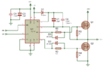
Why did you decide to power your circuit with 18v?i would advice to to use 12v and when ever i am using IR2110 i make sure that my input voltage to the pin 10 and pin12 of the IR2110 shouldn't exceed 5v,
 

Any suggestion for me? Please see post#16 for detail info about the problem and some test cases.
 

I've just made the circuit in another project board and tested with just one MOSFET. MOSFETs switching is while connected in high and low side output separately. While testing the high side output, I've shorted Vs and Source of the MOSFET to Ground. But again when I connected the MOSFETs as half bridge configuration (as like as the the attached circuit given in the earlier posts) the IR2110 became hot and damaged.
 

[NB: I didn't use C2, C3 and C4 which should not be the issue, should it?]

C2 and C4 are important and close to the IC. And The IC should be as close as possible to the MOSFETS. Did you put R1 and R2?
 

Status
Not open for further replies.

Similar threads

Part and Inventory Search

Welcome to EDABoard.com

Sponsor

Back
Top