Continue to Site

Welcome to EDAboard.com

Welcome to our site! EDAboard.com is an international Electronics Discussion Forum focused on EDA software, circuits, schematics, books, theory, papers, asic, pld, 8051, DSP, Network, RF, Analog Design, PCB, Service Manuals... and a whole lot more! To participate you need to register. Registration is free. Click here to register now.

IR2110 LTSPICE Simulation issue

Status
Not open for further replies.

sabu31

Advanced Member level 1
Joined
Jan 28, 2011
Messages
441
Helped
12
Reputation
24
Reaction score
13
Trophy points
1,298
Activity points
5,103
Dear All,

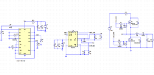
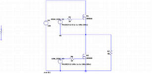
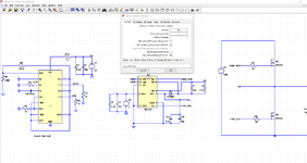
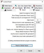
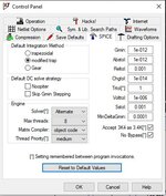
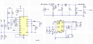
I am trying to simulate an H-Bridge circuit using LTSPICE using IR2110 as a MOSFET driver. However, I am facing an issue with the simulation. It says the simulation step size is too small. Trouble with IRF830 m-1 instance. I am attaching the circuit for your reference. Please let me know what should be done to rectify this issue.

Thanking you.
 

Attachments

  • Half_Bridge_IR2110.png
    Half_Bridge_IR2110.png
    47.6 KB · Views: 152

If the complaint is "timestep too small" then look for a
couple of things.

One is device models which are "too ideal" or "too simple",
lacking capacitances especially, which allows insane node
movement and let solution "get out over its skis" and unable
to back-step (this is wht timestepping fails, it cannot go back
further than the last accepted (even if, or especially if wrongly)
timepoint.

Another is, there's a default behavior for initial timestep. It
is possible that, if you have sources whose "activity rate" is
higher than 1/(tstop/1000) your analysis might entirely miss
an event (or worse, only miss part of its effects and catch
others, resulting in a kind of matrix cognitive dissonance
that could only have been resolved at the time but now is
baked in until solution gives up). So anyway, be sure that
your declared timestep is smaller than your smallest declared
stimulus risetime (which should be smaller than PW and so on).

You might try replacing those IC behaviorals with sources
just for debug, because behavioral models tend to embed
the kinds of too-ideal elements and blind states, which defy
initialization or develop insane intermediate solutions that
blow up instead of converge. If you think it's the FET, take
out everything but the right hand third of the schematic and
make HO, LO be roughly-right pulsed sources. If the problem
is still there, at least you've cut the "location fog" by 2/3.
Swap in somebody else's FET, maybe that "fixes" things.
On and on until it gets on its feet.
 

T
If the complaint is "timestep too small" then look for a
couple of things.

One is device models which are "too ideal" or "too simple",
lacking capacitances especially, which allows insane node
movement and let solution "get out over its skis" and unable
to back-step (this is wht timestepping fails, it cannot go back
further than the last accepted (even if, or especially if wrongly)
timepoint.

Another is, there's a default behavior for initial timestep. It
is possible that, if you have sources whose "activity rate" is
higher than 1/(tstop/1000) your analysis might entirely miss
an event (or worse, only miss part of its effects and catch
others, resulting in a kind of matrix cognitive dissonance
that could only have been resolved at the time but now is
baked in until solution gives up). So anyway, be sure that
your declared timestep is smaller than your smallest declared
stimulus risetime (which should be smaller than PW and so on).

You might try replacing those IC behaviorals with sources
just for debug, because behavioral models tend to embed
the kinds of too-ideal elements and blind states, which defy
initialization or develop insane intermediate solutions that
blow up instead of converge. If you think it's the FET, take
out everything but the right hand third of the schematic and
make HO, LO be roughly-right pulsed sources. If the problem
is still there, at least you've cut the "location fog" by 2/3.
Swap in somebody else's FET, maybe that "fixes" things.
On and on until it gets on its feet.
Thanks for your suggestion. Though I could not understand completely.

As you mentioned, I simplified the circuit by driving the mosfet with voltage source as shown in attached figure(Waveform2). Its working fine.
The TL494 circuit is also working fine individually.

How do i check IR2110 is working both high side and low side. Is there anything else to be done in LTSPICE setting apart from the setting shown in the attached figure (Waveform4).
 

Attachments

  • Waveform_3.png
    Waveform_3.png
    29.8 KB · Views: 103
  • Waveform4.png
    Waveform4.png
    71.5 KB · Views: 97

Hi all,

I solved the time step issue by changing the solver setting to "alternate". This was obtained from Facebook group Power Supply Design . Now I am able to simulate a buck converter.

Though its regulating. There is considerable oscillation in output . Also the PWM is sometimes turning off.
I have used the design example given in attached pdf (except for the device/drive part).

Is there any thing else to be considered/or missing in simulation. I am doubtful regarding the feed back loop.
 

Attachments

  • 79768659_687354341791207_1862086459909996544_n.jpg
    79768659_687354341791207_1862086459909996544_n.jpg
    40.6 KB · Views: 83
  • 79927240_687353838457924_3320656400148856832_n.jpg
    79927240_687353838457924_3320656400148856832_n.jpg
    45.7 KB · Views: 93
  • Waveform_7.png
    Waveform_7.png
    142.7 KB · Views: 90
  • Waveform_6.jpg
    Waveform_6.jpg
    752.7 KB · Views: 92
  • TL494.pdf
    329.8 KB · Views: 92

Hi,

I see too high output voltage ripple with respect to switching frequency.
So either
* increase swithing frequency or
* increase output capacitance.

C3 combined with R15 form a 800Hz filter. I guess your expected switching frequency is around 15kHz. So there is just a ratio of about 1:20.
Over the thumb: your input voltage is 10V so the output ripple may be up to 10V / 20 = 0.5Vpp.
We see about 1Vpp, mybe because of the discontinous switching.

*****
May I ask why you build it this way? I mean there are plenty of ready to buy step down regulators. More reliable, smaller, less part count, optimized efficiency, additional features....

I´d never design such a standard circuit from the scratch.

Klaus


Status
Not open for further replies.

Part and Inventory Search

Welcome to EDABoard.com

Sponsor

Back
Top