Continue to Site

Welcome to EDAboard.com

Welcome to our site! EDAboard.com is an international Electronics Discussion Forum focused on EDA software, circuits, schematics, books, theory, papers, asic, pld, 8051, DSP, Network, RF, Analog Design, PCB, Service Manuals... and a whole lot more! To participate you need to register. Registration is free. Click here to register now.

IR2110 Full Bridge Vdd voltage

Status
Not open for further replies.

kriitish

Newbie level 6
Joined
Jul 17, 2014
Messages
11
Helped
0
Reputation
0
Reaction score
0
Trophy points
1
Activity points
87
Hello Friends,
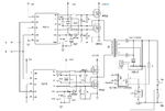
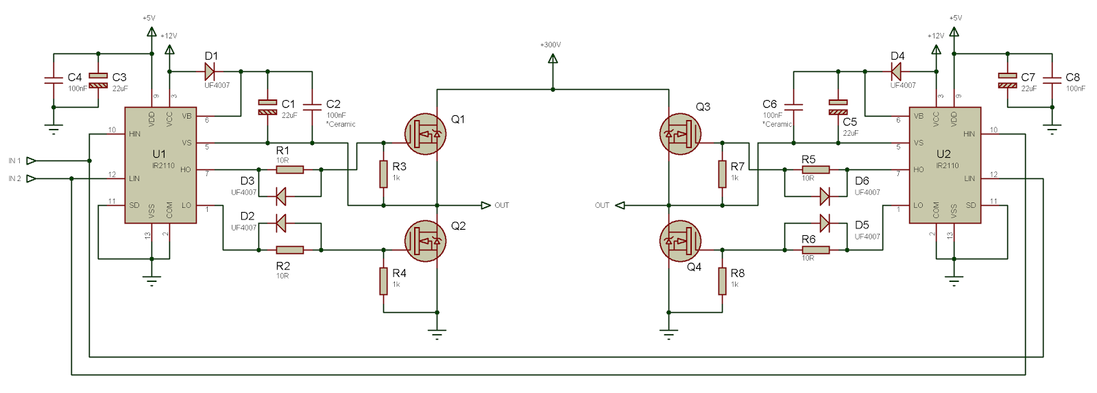
I am designing a IR2110 Full Bridge inverter, in which HIN and LIN comes from SG3525. I use the circuit which I have attached. I got the circuit from Tahmid's blog. I give 12V to VCC and Vb. The inputs HIN & LIN are 8.5V from SG3525. The most bizarre thing I observed is that, when I checked the voltage at pin 9, I get 10.5V. In normal condition pin 9 is a input pin and 5V must be given as input voltage. But I get some output voltage from pin 98-O. I don't know what is happening. Please anyone could help me by telling what mistake I am doing.

Regards,
Kriitish
 

Attachments

  • IR2110 Full Bridge.png
    IR2110 Full Bridge.png
    77.1 KB · Views: 317

You didn't tell what is actually connected to VDD, but you must not drive the logic inputs with a voltage above VDD. Read the datasheet, maximum ratings.
 

Thanks for your reply FvM.
I used LM317 and got 5V output. I hooked the 5V output to the Vdd pin. IR2110 was normal ( which means the Vdd = 5V, Vcc= 12V, Vb= 12V.) when HIN and LIN was not connected. But when I connect HIN and VIN to the output of SG3525 I get 10.35V at pin 9 Vdd.

Regards,
Kriitish
 

Vdd is an input pin, so it must not give any output voltage. I tried to verify whether there is any short circuit in my breadboard, but there isn't any. I thought the IC would have damaged and I replaced with new IC. But still I face the same problem. Please help me.

- - - Updated - - -

Thanks for replying Kappa_am.
I have connected given common ground to two IR2110 ICs and one SG3525. You mean it is a fault ?
 

are there separate supply for SG3525 and drivers? if so I think you have to use a opto between driver and SG to isolate. I think the problem rise because of separate ground of logic inputs and vdd.

lets do some examination, disconnect SG; and use vdd to pull up Hin or Lin. what's happened? this help to find problem.
 
Last edited:

It seems like you didn't read my comment about maximum ratings, or don't understand what maximum ratings are.

If you are driving the input pins above Vdd, the substrate diodes are forward biased and Vdd will be raised to input voltage-0.6 V, if the supply voltage allows it. As long as you don't exceed the maximum pin current, nothing will be damaged.

So say it's normal to supply Vdd with 5V. You should better say, it's normal to power Vdd from the same source as the driving logic, in your case SG3525 Vc (pin 13) voltage.
 
Vdd supports 15V Logic and 3 Terminal regulators will source current but not sink any, hence if the LDO output is pulled up, it doesn't take much current to do so.

However the driver chips indicates.
Vss Logic supply offset voltage w.r.t. COM = Vcc -25 [min] & V + 0.3 [max]
and Iqdd Quiescent for Vdd supply current = 30 uA max.
- meaning it should pull down not up.

try a 1k Load resistor on 5V and check voltage differential between Vss and COM and GND
 

Hi friends,
As Kappa-am and Fvm mentioned about the ground problems, I hooked up the 12V (common supply for SG3525 & IR2110) at the Vdd pin. Now the pin 9 Vdd gets 12V constantly without any problem.
My IR2110 Vcc, Vb, Vdd and SG3525 Vc, Vcc all are connected to 12V supply.

But, only at the LO output pin square wave signals are present, whereas in HO pin I get some unwanted signals. I need help friends.

Regards,
Kriitish
 

Hello Kappa_am,
In IR2110 the Vb receives 11.7 V which is one diode drop below 12V (bootstrap circuitry). When I measure with multimeter the HO output pin shows around 11.5 V ! I measured using multimeter at the LO pin, and it showed 5.15V.
I examined the voltages in oscilloscope, the LO voltage was square wave whereas HO was rugged waveform.

Regards,
Kriitish
 

all voltage measurements are referenced to ground? please measure Vb-Vs and HO-VB. and check Hin. I thing grounding Hin and observing Ho is also good Idea to find the error.
 
Hi friends,
I read the old threads and found that IR2110 works only if it connected with power switches. So I connected the IGBTs with the IR2110. For testing I connected only the half bridge and found that I get square wave signals at the gate. Fine IR2110 is working !

Total peak to peak voltage was 24V and High-+12V; Low- -12V. Is the output what I am getting is right ?

Regards,
Kriitish
 

hello dear

if you are using SG3525 with IR2110.I suggest you to connect VDD,VCC of IR2110 and VCC of SG3525 to same power supply.
Actually u must connect in this way if you supply 5V to VDD and op of SG3525 is 8.5 V then IR2110 will not work.Show graph in datasheet.


VDD should be connected to 5V when u r supplying power from uC.

i was facing same problem with IR2110 + SG3525 but after combining power supply it works well i am using it on 310V DC ...I love IR2110 now.


1 obtain 15V regulated supply
2 give it to IR2110's VCc and VDD,Vb and also to SG3525


-Regards
 

Hi ... I'm using 2 IR2110 and a 7408 AND gate IC for a full H-Bridge to the same connection as fig.8 of Tahmid blog ...


with 8 IR3205 MOSFET's paralleled 2X4 to increase the current capability with a 1k resistor and a reversed 15v-ZDiod gate-to-source for gate protection each ...
the bootstrap capacitors are 47uf and the estimated DC motor current is 80A Vcc=12v ...

I'm suffering from a blown track on the pcb that connects the 12v to pin3 Vcc every time I connect the power ...

when IC's are removed from there sockets that error disappeared ...

Do I have a bad/shorted IC's ? ...
or they want to drag that kind of Amp. due to the motor high current ... so I should provide a thicker track ?

thanks in advance ...
 

Check that the UF4007's are up to the task, possibly replace with STTH1r06 (1A 600V > ultrafast) also try a 4E7 current limiting resistor in series with the diodes
 
OK ... thanks
I've checked the mentioned diodes and they are good ... the issue was with the 7408 AND gate that provides the Hin and Lin ... they were both high due to error in the input signal from Arduino... so there was a shoot through in the IR2110 ... both IR2110 are damaged and replaced ... strangely all MOSFET's are good ... every thing now works fine .

posting a question is really relieving your mind for more thinking .
many thanks to all ...
 

Re your power circuit, you will need a VERY gradual soft start as the peak currents in the mosfets will be very high as the ckt tries to charge the large - initially uncharged - output cap through the transformer (with no o/p inductor).

- - - Updated - - -

You will likely need a 1k across the opto LED to provide the quiescent current for the TL431, else the opto will always be on a little bit. Some fairly generous snubbers across the o/p diodes and the mosfets will likely also be necessary due to the leakage L on the Tx. Even quite narrow volt spikes on the diodes can kill them.
 
Status
Not open for further replies.

Similar threads

Part and Inventory Search

Welcome to EDABoard.com

Sponsor

Back
Top