Continue to Site

Welcome to EDAboard.com

Welcome to our site! EDAboard.com is an international Electronics Discussion Forum focused on EDA software, circuits, schematics, books, theory, papers, asic, pld, 8051, DSP, Network, RF, Analog Design, PCB, Service Manuals... and a whole lot more! To participate you need to register. Registration is free. Click here to register now.

IR Transmitter Help...

Status
Not open for further replies.

amzaiton

Newbie level 3
Newbie level 3
Joined
Apr 23, 2013
Messages
3
Helped
0
Reputation
0
Reaction score
0
Trophy points
1,281
Visit site
Activity points
1,299
Hi,

I've designed my IR transmitter as picture attached and assembled the circuit. My input signal is 10V (peak to peak) sine wave and 500KHz frequency. Unfortunately the output signal I got is being clipped at top and bottom end.. I've tried to recalculate the resistor and capacitor value but it gives the same result..

Please help

Thanks
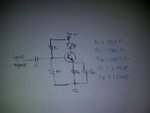

IR Transmitter.jpg
 

Well this clipping that you see is coming because of transistor. When you apply a sinusoid, you are operating your transistor as an amplifier, and at top it gets saturated. Can you put a picture of your output waveform, so that I can help you precisely. BTW you sould take a look at BJT curves.
 

Thanks Shatruddha, this is the waveform from the simulation..

simulation 1.jpg

i've tried to calculate the value based on 2N3904 transistor datasheet, and simulate it again.. the top waveform is the input and the bottom one is the output..
 

well, the problem that I see is that you are providing a negative voltage to your transistor. During that part, your output is clipped and for positive half, you are using amplifier characteristic of transistor and getting the amplified waveform.
 

how to apply positive voltage to the transistor?? i really dont know :sad:
 

Status
Not open for further replies.

Part and Inventory Search

Welcome to EDABoard.com

Sponsor

Back
Top