Continue to Site

Welcome to EDAboard.com

Welcome to our site! EDAboard.com is an international Electronics Discussion Forum focused on EDA software, circuits, schematics, books, theory, papers, asic, pld, 8051, DSP, Network, RF, Analog Design, PCB, Service Manuals... and a whole lot more! To participate you need to register. Registration is free. Click here to register now.

IR Thermopile Temperature Sensor

Status
Not open for further replies.

kuro_ng

Newbie level 6
Joined
Apr 24, 2011
Messages
13
Helped
3
Reputation
6
Reaction score
2
Trophy points
1,283
Activity points
1,418
Hey all,

If anyone who has knowledge on this please help me out, I would really appreciate it.

I"m doing a project which make a Infrared thermometer. The requirement of the project is that I need to do everything so I could not use the awesome MLX90614
HTML:
http://www.sparkfun.com/datasheets/Sensors/Temperature/MLX90614_rev001.pdf
.

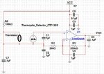
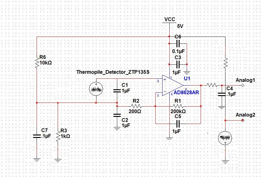
I use the ztp 135 sr as my thermopile
HTML:
http://www.ge-mcs.com/download/temperature/920_159a.pdf
. It is an analog sensor which has ambient thermistor. I use 5 volt supply and I connect my preamp and thermistor from the same supply

What I do is I connect the ztp135 to the low noise, low signal preamp AD8628
HTML:
http://www.ge-mcs.com/download/temperature/920_159a.pdf
with 1000 gain. The output from the ztp135 is around 1.8 mV then 1000 gain with capacitors involved I got out only .288 V but it's increase when I point the sensor ztp135 to a high temperature. So I'm assume I'm doing right.

The question I want to ask is how could I connect the signal out from preamp AD8628 to the micro-controller to test if the whole signal I make is working, cause right now I can only see the voltage increase if I point to higher temperature.
I'm using the ATMEGA328
HTML:
http://www.atmel.com/dyn/products/product_card.asp?part_id=4720
which has the analog to digital converter option.
Do I need to connect to an I2C bus then connect to the ATMEGA 328? I asked so because most of the example I see they using the I2C bus which is the MLX90614 has. If I have to, how would I connect my preamp output to it, and what is the specific I2C product that I could use.

Thanks you very much to take ur time to help me out. Any suggestion would be appreciated.
 

The output from the ztp135 is around 1.8 mV then 1000 gain with capacitors involved I got out only .288 V
I don't understand, how capacitors would reduce the gain of a thermopile amplifier, which should be basically DC capable for a thermometer.
 

I don't understand, how capacitors would reduce the gain of a thermopile amplifier, which should be basically DC capable for a thermometer.

I think the gain itself is 1000 times. However the measurement i got is temperature dependent. If I actually touched the sensor's surface it would go up to 2 something voltage though. I know that's too much offset, however I try to learn how to connect to the microcontroller so I could see the actual temperature and try to calibrate it.

I insert the schematic that I did. Could you please take a look at it :)
 

Attachments

  • Capture.JPG
    Capture.JPG
    149 KB · Views: 427
Last edited:

Two comments on the schematic:
-The "virtual ground" circuit doesn't look good. You should have a voltage divider of considerably lower resistance.
-A capcitive load of 100 nF will bring up oscillations. If you want it as filter, place a series resistor between OP output and capacitor.

Generally, the reference temperature information available from the thermistor would be needed for a thermometer. You can feed it to a second analog channel.
 
Thanks for you help FvM.
+ How lower would u suggest that I should use?
+ So I should use .1 uF for all of my capacitors?
The capacitor under the 200K is working at the filter already.
When you said the reference temp information from thermistor would needed to feed to the second analog channel, How could I connect it? because basically the thermistor has 2 pin, one is ground, one is connect to the 5V.
the main question I want to know is how could connect to the microcontroller without the SDA and SCL? Do I need to connect to some kind of mux that has I2C (which has SDA and SCL) the connect to the microcontroller?

That's alot of questions but I really need yours and anyone who has knowledge of this help me out. really appreciate it .
 

I thought of a lower resistance voltage divider formed by R6 and a resistor in parallel to C7, in the lower kohm range. Assuming the thermopile has a mainly positive output voltage, the divider can be made asymmetrical, e.g. 10k to 1k.

The thermistor can be connected in a simple voltage divider circuit, feeding directly an analog processor pin. You have to refer to the exponential thermistor characteristic to calculate temperature from voltage respectively resistance. Thermistor - Wikipedia, the free encyclopedia

There's no use for an I2C interface in your project so far. Or is it intended to send measurent data to a different device?
 
Thanks FvM.
I don't intend to send to anything except give the value to LCD.
Sorry for my lag of knowledge, but how would u calculate it? I read the article u send but doesn't make sense. I know that thermistor resistance of ztp135 is 100+- %3 @ 25C (77F) from the datasheet.
I might understand ur wrong, but I change my diagram to this. Please take a look at it if I understand ur correctly. thanks alot. Capture.JPG
Really appreciate ur help :)
 

You have been mixing two unrelated points from my post, and ignored a third one. See below an aproximate circuit representation of my suggestions.

 
wow, nice.
but would it be ok if the voltage divider's out put connect to the thermopile? I thought thermopile itself general voltage already.
On the other hand for the thermistor would I need to rotate the - and + sign? because right now the supply connect to the negative sign, or it meant to be like this for ambient temperature purpose.
Thanks for go extra mile to help me FvM.
P/S: how u change the circuit ? are you using photoshop or something lol?
 

The voltage divider is providing a virtual ground for the circuit. It's required to operate the OP with single supply. It's not interfering with the thermopile output voltage, but shifting all node voltages by 0.5V.

Normally, a thermistor is just a temperature dependent resistor and doesn't expose a polarity. Otherwise it has to be reversed of course.

I use to edit these images with standard Windows Paint.
 
I see. how would test it to see if the circuit is working FvM.
with the original circuit i connect the ouput (from the opamp) and the ground cable to precise multimeter. I got around .26 V as I mentioned, it's increase when I put my hand over or put some thing hot on it.
I've connect the circuit that u give, I tested with both analog to multimeter with give me around .8V however the voltage doesn't change at all when I move my hand over, then I test the same way to each analog with ground, but come out only .03 V and no change after I move my hand over :(. do you have any suggestion about this? :(
 

I don't see a reason, wha the circuit isn't working. The thermistor part can be ignored so far, but the thermo pile/OP part should work.
 

yeah. it's abit weird. I have reconnected 2 times aready, the result came out the same. I've will carefully check it over and reconnect them again. :)
 

I must admit, that I also can't explain, how the original circuit would achieve the said about 0.3 V bias point. The 100k resistor is expected to pull both OP inputs up. Thus I wonder, if the real circuit has been different from schematic.
 

hey FvM, sorry for late reply. this is a general diagram that I cameup with. It's different from the old one is that I dont connect power supply to the thermistor. I wonder what I'm doing is right or not? With the ambient thermistor's output and thermopile's output.IMAG0017.jpg, usually how much do we need for it? when both signal plug to ADC, it doesn't matter which channel I connect? (channel 0, channel1).
 

The thermopile amplifier misses an input bias and can't work.

For the thermistor, which is just a temperature dependent resistor and not a voltage source like the thermopile, no amplifier is required. As previously suggested, I can be put in a simple voltage divider with a fixed resistor.
 
Thanks FvM.

1. So I need to have a third resistor that equal R1 // R2 on positive terminal on the thermopile ampifier?

2. The thermistor itself output is really small, as mall as the thermopile, that why I put an amplifier infront of it. Right now I still not clear on the ambient compensation. Sorry for being slow, but I have read couple article about it. All I understand that we could get the output of thermopile amplifier - output of thermistor or reverse, and that result would convert to actual object temperature.
That's why I use the ADC to do the job.

Could you please explain it to me on the ambient compensation part in this design ? I would really appreciate it. Many Thanks.
 
So I need to have a third resistor that equal R1 // R2 on positive terminal on the thermopile ampifier?
No. The amplifier circuit needs a virtual ground, like previously suggested in post #8.
The thermistor itself output is really small
As said it's a resistor. It has no "output" on it's own. When designing a voltage divider, the fixed resistor value should be in the same order of magnitude as the thermistor resistance, about 100K, if I remember the datasheet right. The circuit can be according to post #8 as well.
Could you please explain it to me on the ambient compensation part in this design ?
In a slightly simplified view, the thermopile measures a temperature difference between an object and the thermopile temperature. To get the object temperature, you have to add both measurements. I have describe in post #6, how the thermistor measurement can be converted to a temperature value.
 
Thanks for replying FvM, your comments are so helpful :).

This is the first diagram that I come up with before your post 18 . IMAG0020.jpg

But after that, I base on your comment and post 8 to redraw it. Could you please give comment on this diagram. IMAG0019.jpg

I used ADC to add those to signal together in digital way. would it be right? or I need a create a saperated analogue opamp (or buy one that you know of) to add those to signal together.

Thanks alot,
Sincere
 
In my opinion, the second diagram is right, performing the temperature compensation in digital signal processing. The voltage level of 0.22 V for the virtual ground (10K/0.47K) is suitable according to my knowledge of the OP data.
 
Status
Not open for further replies.

Similar threads

Part and Inventory Search

Welcome to EDABoard.com

Sponsor

Back
Top