Continue to Site

Welcome to EDAboard.com

Welcome to our site! EDAboard.com is an international Electronics Discussion Forum focused on EDA software, circuits, schematics, books, theory, papers, asic, pld, 8051, DSP, Network, RF, Analog Design, PCB, Service Manuals... and a whole lot more! To participate you need to register. Registration is free. Click here to register now.

IR receiver frequency modulation

Status
Not open for further replies.

grillz58

Newbie level 4
Joined
Jul 14, 2010
Messages
6
Helped
0
Reputation
0
Reaction score
0
Trophy points
1,281
Activity points
1,315
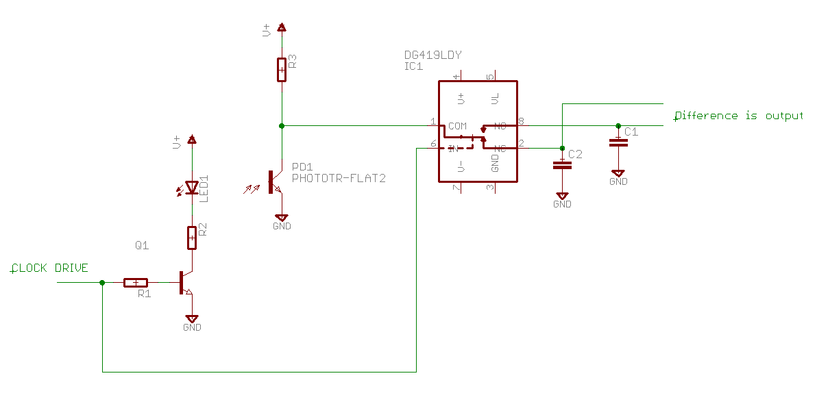
I'm working on a project that uses a set of IR emitter and detectors. The emitter are modulated to 35hHz to 40kHz. But I am having a hard time trying to find a way to modulate the detectors (L14G2 phototransistors) to the corresponding frequencies.

thanks in advance
 

I don't understand what you mean by "modulate the detectors". The detector signal should be filtered to suit the emitter modulation, not modulated.

Keith
 

that's what i meant. how should i set up the detector circuit to filter a frequency?
 

I am slightly puzzled by your reference to frequency modulation. That term refers to using a carrier frequency and then modulating the frequency of the carrier to transmit information - either digital or analogue. Is that what you are doing? Or are you actually amplitude modulating at a fixed modulation frequency? The demodulation of each type is totally different.

Keith
 

I am using a 555 timer in an oscillator circuit to generate a 20k to 40k Hz pulse that drives the LED.
No information is transferred. The receiver just has to detect whether the LED of this frequency is blocked or not.

thanks for your patience
 

OK, you are really amplitude modulating it then. There are detectors which have built in filtering but they may no be suitable for you because of your wide range of input frequency. Unless you can control the modulation frequency within a narrow range then you may need to use a low pass and high pass filter to give a broad bandpass.

Are you able too connect you transmitter and receiver. If so, you could use synchronous demodulation. You use the modulating signal to drive a couple of sample and hold circuits. The difference between the two sample and hold outputs will be the received signal.

Keith
 

Yes I am able to connector transmitter and receiver.
Is it possible if I just connect the receiver to the 555 timer to synchronize them?
 

Yes, pretty much. You can use an analogue switch to sample the signal when the LED is on and also when it is off. The difference is your received (modulated) signal level.

Keith
 

when I connect the phototransistor to 555 timer output. it will recognize a constant high. since the output is supplying power to the LED as well.
 

thanks a lot for the help. the matching filter should work
 

Status
Not open for further replies.

Similar threads

Part and Inventory Search

Welcome to EDABoard.com

Sponsor

Back
Top