Continue to Site

Welcome to EDAboard.com

Welcome to our site! EDAboard.com is an international Electronics Discussion Forum focused on EDA software, circuits, schematics, books, theory, papers, asic, pld, 8051, DSP, Network, RF, Analog Design, PCB, Service Manuals... and a whole lot more! To participate you need to register. Registration is free. Click here to register now.

IO-202 oscilloscope CRT substitution

Status
Not open for further replies.

neazoi

Advanced Member level 6
Joined
Jan 5, 2008
Messages
4,122
Helped
13
Reputation
26
Reaction score
15
Trophy points
1,318
Location
Greece
Activity points
36,951
Hello,
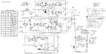
I have this old oscilloscope. I need to ask a few basic questions based on your experience:

1. Will I be able to substitute the CRT with another one (probably smaller in size) and re-calibrate the amplifiers for the new CRT used? (assumming proper CRT voltage adjustments)

2. If I use this oscilloscope (5MHz) as an output to a 100MHz spectrum analyzer (which outputs X,Y signals) will I be able to display the frequency range of 100MHz with this 5MHz oscilloscope or do I need amplifiers that can do 100MHz?

3. Is there any simpler osciloscope to build using descrete components (still useable op to a few MHz) than this one?
 

Attachments

  • io-102.gif
    io-102.gif
    297.4 KB · Views: 83

1.
I guess it's possible to make the necessary changes, but for the moment we are unable to access the attached diagram.

2. If I use this oscilloscope (5MHz) as an output to a 100MHz spectrum analyzer (which outputs X,Y signals) will I be able to display the frequency range of 100MHz with this 5MHz oscilloscope or do I need amplifiers that can do 100MHz?
A spectrum analyzer include its own sawtooth generator to drive the oscilloscope in the XY mode or synchronize the internal sawtooth generator in the oscilloscope. Almost any oscilloscope can be used as a display for the spectrum analyzer.
 
  • Like
Reactions: neazoi

    neazoi

    Points: 2
    Helpful Answer Positive Rating
Consider how a spectrum analyzer works and you'll see, that the RF bandwidth hasn't to do with the display bandwidth respectively scan speed.
 
  • Like
Reactions: neazoi

    neazoi

    Points: 2
    Helpful Answer Positive Rating
1.
I guess it's possible to make the necessary changes, but for the moment we are unable to access the attached diagram.

Thank you very much for your replies. Here is the diagram. **broken link removed**

I like it's simplicity, but I would like to replace the CRT with a more modern one, smaller in size, and maybe a lower anode volrage one, so I guess I would reduce the voltage of the PSU.

But what about the diflection amplifiers? how should I re-tune them to respond to the new CRT?
 

Status
Not open for further replies.

Similar threads

Part and Inventory Search

Welcome to EDABoard.com

Sponsor

Back
Top