Continue to Site

Welcome to EDAboard.com

Welcome to our site! EDAboard.com is an international Electronics Discussion Forum focused on EDA software, circuits, schematics, books, theory, papers, asic, pld, 8051, DSP, Network, RF, Analog Design, PCB, Service Manuals... and a whole lot more! To participate you need to register. Registration is free. Click here to register now.

[SOLVED] Inverting AC amplifier using OpAmp - problem with output (oscillations?)

Status
Not open for further replies.

prateek_k_chd

Member level 5
Joined
Sep 25, 2009
Messages
87
Helped
3
Reputation
6
Reaction score
2
Trophy points
1,288
Activity points
1,988
Hi all !
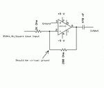
This is my circuit :
eda.gif

With the given configuration,I should have about 0.080 V of 950Hz AC (~50% duty cycle) at the output

However,I get almost 2Volts of 1900Hz AC at 96% duty cycle at the output.
Moreover,the inverting terminal should be nearly at ground.But I read 2.4 Volts Ac at that point (~50% duty cycle).

Also, another strange thing is that as I INCREASE the feedback resistance,the output voltage DECREASES.

However ,this circuit operates correctly when the resistances involved are higher. For instance,if Rf=5k and R1=10k then I do read 4V ac at output (950Hz @ 50% duty cycle) and the inverting terminal is nearly at ground too.


From my limited knowledge of analog circuits,I infer that the problem might be due to inadvertently occurring oscillations (since the output frequency doubles and duty cycle too almost doubles).

Please advice me on this ! What could be the cause? And a possible solution ?
Thank you so much :smile:
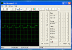
 

Update : I just checked with a PC based CRO - It shows that the frequency doesn't change : The symmetry of the wave changes. As the feedback resistance increases, the output wave swings less and less below 0v and the multimeter probably interprets this as increased frequency. (This is also likely because with increase in feedback resistance,the frequency reading on the multimeter becomes unstable)

Attached screenshot of output ( at Rf of about 700 ohms ) : Clipboard01.gif

However,my problem remains unsolved - Increasing feedback resistance causes output to decrease ,whereas it should increase !

Please help !!!
 

I think the problem could be twofold:

* At first, the opamp is operated with a gain less than unity (strong feedback). This is always critical for unity-gain compensated opamps.
* Secondly, the load (rather small feedback resistor together with capacitive loading) makes the situation even worse.

So, why not use a larger feedback resistor?
If necessary you can try - in addition - an external compensation scheme (at the opamp inpu).

---------- Post added at 17:13 ---------- Previous post was at 17:00 ----------

Another option would be decoupling of the load capacitor (if it really is necessary). At first, try measurements/simulations without Cload.
 
Thanks LvW !
The measurements and simulations without Cap do not throw up any abnormality. In fact,the simulation with the cap also does not show any problem
Anyways,I tried a 741 instead of 3140 - the circuit now works ! [ Albeit it still fails when the resistances are still lower -- R1=200 Ohms and Rf=20 ohms . I need this config to work too :( . I guess I need to try other opamps.]
 

Questions:

Your schematic shows your non-inverting input ( pin 3 ) is labelled 'ground'. Suggesting it's connected directly to zero ground.

Did you connect it to the joining point between the power supplies?

And is it a direct connection? Or did you put a resistance in the wire?

Because it's usually recommended to install the same value resistance at both inputs of an op amp. I believe the idea is to reduce imbalances in the internal current mirror, and thus reduce rogue oscillations, etc.
 
Last edited:
...it still fails when the resistances are still lower -- R1=200 Ohms and Rf=20 ohms . I need this config to work too

Normally, feedback resistors are used (and should be used!!) that are much larger than the internal output resistance of the opamp (app. Rout=50...100 ohms).
Otherwise, all formulas (neglecting the influence of Rout) are not valid anymore.
More than that, such a small feedback resistor brings the output current capability of the opamp to its limits.
 
@BradtheRad : No,it's not physically connected to ground. Just that acc. to opamp theory,this pin should be almost at ground. As for the inv terminal,I did have a resistance from it to ground but that didn't seem to be making any difference....so I've removed it.

@LvW : I have experimented a bit and found that the R1 matters a lot here...and I'm able to achieve stability even with Rf of about 10 ohms if the R1 is 500ohms or more.....So my problem is more or less solved.

Thanx a lot guys for suggestions !
 

CA3140 datasheet has some information about available output current. You'll notice, that particularly sink current is rather limited. The feedback network is however contributing to load resistance. Apparently, you're yet ignoring OP output drive capability in your circuit design.

At first, the opamp is operated with a gain less than unity (strong feedback). This is always critical for unity-gain compensated opamps.
I don't see a problem in this regard. Unity-gain compensation refers to non-inverting configuration, in other words feedback factor k = -1. A low gain inverting configuration as used in the present circuit has still k >-1.
 

.........
I don't see a problem in this regard. Unity-gain compensation refers to non-inverting configuration, in other words feedback factor k = -1. A low gain inverting configuration as used in the present circuit has still k >-1.

OK, FvM - most probably there will be no real "problem". Agreed - if the feedback action alone contributes to potential instabilities.
Nevertheless, the phase margin certainly will drop by several degrees if you lower the inverting gain from (let's say) -1 to -0.1 (LM741 simulations show a margin difference of approx. 10 degrees).
I think, this effect can - under worst case conditions - sum up with some other unwanted parasitic influences and, thus, lead to oscillations.
 

Status
Not open for further replies.

Part and Inventory Search

Welcome to EDABoard.com

Sponsor

Back
Top