Continue to Site

Welcome to EDAboard.com

Welcome to our site! EDAboard.com is an international Electronics Discussion Forum focused on EDA software, circuits, schematics, books, theory, papers, asic, pld, 8051, DSP, Network, RF, Analog Design, PCB, Service Manuals... and a whole lot more! To participate you need to register. Registration is free. Click here to register now.

interfacing ultrasonic sensors

Status
Not open for further replies.

Rahul Kumar Vashistha

Newbie level 4
Joined
Mar 5, 2015
Messages
7
Helped
0
Reputation
0
Reaction score
0
Trophy points
1
Activity points
83
guys please help me out!
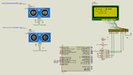
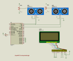
i am trying to interface two ultrasonic sensors(HC-SR04) with pic16f877a and accordingly have written the code as shown below:-


Code C - [expand]
1
2
3
4
5
6
7
8
9
10
11
12
13
14
15
16
17
18
19
20
21
22
23
24
25
26
27
28
29
30
31
32
33
34
35
36
37
38
39
40
41
42
43
44
45
46
47
48
49
50
51
52
53
54
55
56
57
58
59
60
61
62
63
64
65
66
67
68
69
70
71
72
73
74
75
76
77
78
79
80
81
82
83
84
85
86
87
88
89
90
91
92
93
94
95
96
97
98
99
100
101
102
103
104
105
106
107
108
109
110
111
112
113
114
115
116
117
118
119
120
121
122
123
124
125
126
127
128
129
130
131
132
133
134
135
136
137
138
139
140
141
142
143
144
145
146
147
148
149
150
151
152
153
154
155
156
157
158
159
160
161
162
163
164
165
166
167
168
169
170
171
172
173
174
175
176
177
178
179
180
181
182
183
184
185
186
187
188
189
190
191
192
193
194
195
196
197
198
199
200
201
202
203
204
205
206
207
208
209
210
211
212
213
214
215
216
217
218
219
220
221
222
223
224
225
226
227
228
229
230
231
232
233
234
235
236
237
238
239
240
241
242
243
244
245
246
247
248
249
250
251
252
253
254
255
256
257
258
259
260
261
262
263
264
265
266
267
268
269
270
271
272
273
274
275
276
277
278
279
280
281
282
283
284
285
286
287
288
289
290
291
292
293
294
295
296
297
298
299
300
301
302
303
304
305
306
307
#define _XTAL_FREQ 8000000
 
#define RS RD2
#define EN RD3
#define D4 RD4
#define D5 RD5
#define D6 RD6
#define D7 RD7
 
#include <xc.h>
#include <pic16f877a.h>
void Lcd_Port(char a);
void Lcd_Cmd(char a);
void Lcd_Set_Cursor(char a, char b);
Lcd_Clear();
void Lcd_Init();
void Lcd_Write_String(char *a);
void Lcd_Shift_Right();
void Lcd_Shift_Left();
void Lcd_Write_Char(char a);
void sendo();
 
// BEGIN CONFIG
#pragma config FOSC = HS // Oscillator Selection bits (HS oscillator)
#pragma config WDTE = OFF // Watchdog Timer Enable bit (WDT enabled)
#pragma config PWRTE = OFF // Power-up Timer Enable bit (PWRT disabled)
#pragma config BOREN = ON // Brown-out Reset Enable bit (BOR enabled)
#pragma config LVP = OFF // Low-Voltage (Single-Supply) In-Circuit Serial Programming Enable bit (RB3 is digital I/O, HV on MCLR must be used for programming)
#pragma config CPD = OFF // Data EEPROM Memory Code Protection bit (Data EEPROM code protection off)
#pragma config WRT = OFF // Flash Program Memory Write Enable bits (Write protection off; all program memory may be written to by EECON control)
#pragma config CP = OFF // Flash Program Memory Code Protection bit (Code protection off)
//END CONFIG
 
int a;
 
void interrupt echo()
{
  if(RBIF == 1)                 //Makes sure that it is PORTB On-Change Interrupt
  {
    RBIE = 0;                   //Disable On-Change Interrupt
    if(RB4==1 && RB5==1)   
{
      TMR1ON = 1;
      if((RB4==0)|| (RB5==0))
     TMR1ON=0;  
     a = (TMR1L | (TMR1H<<8))/58.82;
      a=a+1;
    if(a>=2 && a<=400)          
    {
      Lcd_Clear();
        Lcd_Set_Cursor(1,1);
      Lcd_Write_String("Speedbreaker");
      Lcd_Set_Cursor(2,1);
      Lcd_Write_String("Distance = ");
      
      Lcd_Set_Cursor(2,14);
      Lcd_Write_Char(a%10 + 48);
 
      a = a/10;
      Lcd_Set_Cursor(2,13);
      Lcd_Write_Char(a%10 + 48);
 
      a = a/10;
      Lcd_Set_Cursor(2,12);
      Lcd_Write_Char(a%10 + 48);
 
      Lcd_Set_Cursor(2,15);
      Lcd_Write_String("cm");
    }
    else
    {
      Lcd_Clear();
      Lcd_Set_Cursor(1,1);
      Lcd_Write_String(" of Range");
    }
    __delay_ms(400);        
        //sendo();
 }                          
    if(RB4 == 1 || RB5==1)                  
    {
      TMR1ON = 1;                    
     }
   if(RB4==0 || RB5==0)              
    {
      TMR1ON = 0;                    //Stop Timer
      a = (TMR1L | (TMR1H<<8))/58.82;  //Calculate Distance
    }
  }
  RBIF = 0;                     //Clear PORTB On-Change Interrupt flag
  RBIE = 1;                     //Enable PORTB On-Change Interrupt
}
 
 
void main()
{
  TRISB = 0b00110000;   //RB4 as Input PIN (ECHO)
  TRISD = 0x00; // LCD Pins as Output
  GIE = 1;                      //Global Interrupt Enable
  RBIF = 0;                     //Clear PORTB On-Change Interrupt Flag
  RBIE = 1;                     //Enable PORTB On-Change Interrupt
 
  Lcd_Init();
 
  Lcd_Set_Cursor(1,1);
  Lcd_Write_String("yo");
  Lcd_Set_Cursor(2,1);
  Lcd_Write_String("mAn");
 
  __delay_ms(3000);
  Lcd_Clear();
 
  T1CON = 0x10;                 //Initialize Timer Module
 
  while(1)
  {
    TMR1H = 0;                  //Sets the Initial Value of Timer
    TMR1L = 0;                  //Sets the Initial Value of Timer
 
    RB0 = 1;               //TRIGGER HIGH
    __delay_us(10);               //10uS Delay
    RB0 = 0;               //TRIGGER LOW
 
    __delay_ms(100); //Waiting for ECHO
    a = a + 1; //Error Correction Constant
 
    if(a>=2 && a<=400)          //Check whether the result is valid or not
    {
      Lcd_Clear();
      Lcd_Set_Cursor(1,1);
      Lcd_Write_String("Distance = ");
      
      Lcd_Set_Cursor(1,14);
      Lcd_Write_Char(a%10 + 48);
 
      a = a/10;
      Lcd_Set_Cursor(1,13);
      Lcd_Write_Char(a%10 + 48);
 
      a = a/10;
      Lcd_Set_Cursor(1,12);
      Lcd_Write_Char(a%10 + 48);
 
      Lcd_Set_Cursor(1,15);
      Lcd_Write_String("cm");
    }
    else
    {
      Lcd_Clear();
      Lcd_Set_Cursor(1,1);
      Lcd_Write_String("Out of Range");
    }
    __delay_ms(400);
  }
}
//LCD Functions
 
 
void Lcd_Port(char a)
{
    if(a & 1)
        D4 = 1;
    else
        D4 = 0;
 
    if(a & 2)
        D5 = 1;
    else
        D5 = 0;
 
    if(a & 4)
        D6 = 1;
    else
        D6 = 0;
 
    if(a & 8)
        D7 = 1;
    else
        D7 = 0;
}
void Lcd_Cmd(char a)
{
    RS = 0;             // => RS = 0
    Lcd_Port(a);
    EN  = 1;             // => E = 1
        __delay_ms(4);
        EN  = 0;             // => E = 0
}
 
Lcd_Clear()
{
    Lcd_Cmd(0);
    Lcd_Cmd(1);
}
 
void Lcd_Set_Cursor(char a, char b)
{
    char temp,z,y;
    if(a == 1)
    {
      temp = 0x80 + b - 1;
        z = temp>>4; //10000000,z=00001000 
        y = temp & 0x0F; //10000000 & 00001111 = 0
        Lcd_Cmd(z);//
        Lcd_Cmd(y);
    }
    else if(a == 2)
    {
        temp = 0xC0 + b - 1; //11000000
        z = temp>>4;//00001100
        y = temp & 0x0F;//0000
        Lcd_Cmd(z);//0X0C
        Lcd_Cmd(y);//0x00
    }
}
 
void Lcd_Init()
{
  Lcd_Port(0x00);
   __delay_ms(20);
  Lcd_Cmd(0x03);
    __delay_ms(5);
  Lcd_Cmd(0x03);
    __delay_ms(11);
  Lcd_Cmd(0x03);
 
  Lcd_Cmd(0x02);
  Lcd_Cmd(0x02);
  Lcd_Cmd(0x08);
  Lcd_Cmd(0x00);
  Lcd_Cmd(0x0C);
  Lcd_Cmd(0x00);
  Lcd_Cmd(0x06);
}
 
void Lcd_Write_Char(char a)
{
   char temp,y;
   temp = a&0x0F;
   y = a&0xF0;
   RS = 1;             // => RS = 1
   Lcd_Port(y>>4);             
   EN = 1;
   __delay_us(40);
   EN = 0;
   Lcd_Port(temp);
   EN = 1;
   __delay_us(40);
   EN = 0;
}
 
void Lcd_Write_String(char *a)
{
    int i;
    for(i=0;a[i]!='\0';i++)
       Lcd_Write_Char(a[i]);
}
 
void Lcd_Shift_Right()
{
    Lcd_Cmd(0x01);
    Lcd_Cmd(0x0C);
}
 
void Lcd_Shift_Left()
{
    Lcd_Cmd(0x01);
    Lcd_Cmd(0x08);
}
 
 
/*void sendo()
{
    if(RB4!=1)
    {
     TMR1ON=0;  
     a = (TMR1L | (TMR1H<<8))/58.82;
    }
    if(a>=2 && a<=400)         
    {
      Lcd_Clear();
        Lcd_Set_Cursor(1,1);
      Lcd_Write_String("Speedbreaker");
      Lcd_Set_Cursor(2,1);
      Lcd_Write_String("Distance = ");
      
      Lcd_Set_Cursor(2,14);
      Lcd_Write_Char(a%10 + 48);
 
      a = a/10;
      Lcd_Set_Cursor(2,13);
      Lcd_Write_Char(a%10 + 48);
 
      a = a/10;
      Lcd_Set_Cursor(2,12);
      Lcd_Write_Char(a%10 + 48);
 
      Lcd_Set_Cursor(2,15);
      Lcd_Write_String("cm");
    }
    else
    {
      Lcd_Clear();
      Lcd_Set_Cursor(1,1);
      Lcd_Write_String(" of Range");
    }
    __delay_ms(400);
 }


tried simulating in proteus but i am getting undesired o/p.
please help..
 

Try using INTx pin and just toggle the INTEDGx when echo is received. Also use a timer interrupt that is when low to high edge is detected, start timer and when high to low edge is detected, stop the timer. additionally use a counter and increment if timer overflows. Use overflow value and timer value and do the maths to get the distance in cm.
 

i did the same..have a look at the code..help me with the function of interrupt that would get called whenever an interrupt will be generated by the timer after overflow.

- - - Updated - - -

Actually my aim is to receive the echo signal simultaneously from both the echo pin of sensors and print the result as speed breaker is detected.. if i am receiving signal at echo pins at different times i must get the distance of the smaller obstacle present in front of the ultrasonic sensor..
 

Is your circuit like this ?
 

Attachments

  • schematic.png
    schematic.png
    36.2 KB · Views: 82
Yesss.. Absolutely identical
Now please please please can you give me the c code for that interfacing..
Or any other kind help related to this project would also be appreciated.. :-D
 

Yup.. . That's what I want and I am using pic16877a it has only one 16bit timer(timer1)..That's why I have to use only one timer i. email timer 1 of pic16877a..
 

PIC16F877A also has Timer0 and I guess it also has Timer3.
 

i know..but 16bit is required..help me with the code..i am runnning out of time..
 

I need some time to write the code. You have to save the timer values into two different variables one for sensor 1 and one for sensor 2 and then do the calculation. I will find a way to do it.
 
Try the attached .hex file in Proteus and also hardware. I have used PIC18F45K22 and 20 MHz external crystal. I have used one timer (Timer1) interrupt and RBIF. See attached image for circuit. Proteus 8.1 SP1 format file attached. I have not tested in hardware.

- - - Updated - - -

One HC-SR04 version .hex file and Proteus simulation. Test in hardware and reply. It uses PIC18F45K22 at 20 MHz external crystal. RB0 is ECHO and RB1 is TRIGGER.
 

Attachments

  • 2x_HC SR04_Distance_Measurement_PIC18F45K22_20MHz.rar
    71.6 KB · Views: 53
  • 2x_Usonic_HC-SR04.png
    2x_Usonic_HC-SR04.png
    49.6 KB · Views: 69
  • HC SR04 Distance Measurement.rar
    53.1 KB · Views: 53

Please keep the two sensors in opposite direction and test the readings. I am not sure but I think that if two sensors are kept close to each other then USonic burst of one will affect the other sensor.
 

PIC12F1840 + HC-SR04 .hex file and Proteus file attached.
 

Attachments

  • hcsr04.png
    hcsr04.png
    24.9 KB · Views: 60
  • PIC12F1840 + HC-SR04.rar
    37 KB · Views: 38

Status
Not open for further replies.

Similar threads

Part and Inventory Search

Welcome to EDABoard.com

Sponsor

Back
Top