Continue to Site

Welcome to EDAboard.com

Welcome to our site! EDAboard.com is an international Electronics Discussion Forum focused on EDA software, circuits, schematics, books, theory, papers, asic, pld, 8051, DSP, Network, RF, Analog Design, PCB, Service Manuals... and a whole lot more! To participate you need to register. Registration is free. Click here to register now.

Inrush managment in hardware for offline PSU?

Status
Not open for further replies.

cupoftea

Advanced Member level 5
Joined
Jun 13, 2021
Messages
2,576
Helped
54
Reputation
108
Reaction score
115
Trophy points
63
Activity points
13,530
Hi,
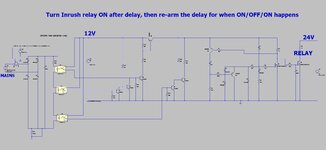
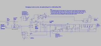
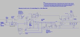
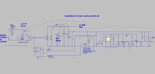
Doing a 4kW offline PSU with inrush management. The attached seems to be the smallest circuitry that can do it all in hardware. (LTspice sim and jpeg schem)
All it has to do is turn the inrush relay ON after a delay after power up. Also, to re-arm the delay, ready for an ON/OFF/ON restart. Also, to make sure the inrush relay doesn’t unwantedly turn off due to the 24V internal PSU powering down due to undervoltage.

Can you think of a lower component count way?
 

Attachments

  • Mains inrush management to 4kW offline PSU.zip
    5.8 KB · Views: 109
  • Inrush management for 4kW offline PSU.jpg
    Inrush management for 4kW offline PSU.jpg
    214.9 KB · Views: 125

Woops , sorry to come back....ive honed it down a little as attached......but any more simplifications?....

Also, some kind of simple manual thing where a manual switch was only "enabled" whenever the caps were full would be fine...as this is only a prototype.
 

Attachments

  • Inrush protection_2.jpg
    Inrush protection_2.jpg
    229.3 KB · Views: 106
  • Mains inrush management to 4kW offline PSU_improved.zip
    5.7 KB · Views: 109

Actually, a long , and very robust delay is needed for the delay to switch the inrush resistors out.......has to be robust because an un-limited inrush from 240VAC mains peak into 4m3 will kill the PSU and blow the breakers, as you know....though can you think of how to reduce the component count here?...without using a micro
LTspice and scm attached.
 

Attachments

  • inrush delay _555 delay.zip
    4.3 KB · Views: 93
  • Long delay for inrush resistor switch out.jpg
    Long delay for inrush resistor switch out.jpg
    158 KB · Views: 109

Hi,

Without understanding your circuit too much... You have a DC supply for a control circuit, right? And presumably (hopefully) the control circuit/brain is up and running before the inrush and fireworks start (!)? a long , and very robust delay - What is robust in this context, please? For now, I assume you mean consistent/reliably repeatable every time, or literally rugged, perhaps?

What comes to mind, without thinking too much of the ins-and-outs of the suggestion, is e.g. a (fast) comparator sensing power in/power on via a divided down voltage and it triggering a timer IC such as the 555, which is capable of very long times indeed when cascaded, or any other timer IC, and I assume you mean a few seconds and not minutes or hours.

Even a sensing circuit maybe, probably really hard to put together, I know, you're the expert, I'm not, that senses when the inrush current is over by e.g. charging a capacitor (the rudimentary clock) that when it reaches x voltage, triggers a comparator to switch out the inrush relay.

If I'm understanding the design goal, I'd consider 'like clockwork' (sequential) rather than 'one response only every time' solutions - Sod's Law says that a circuit that doesn't respond to the circumstances might not always go as planned/intended, a 'thinking/seeing > acting in consequence' solution might be wiser.

You can do start-up delays and switch-outs after x time with a single MOSFET and an RC on the gate, a very small solution indeed, and it's Tau-based (simple maths) and quick to simulate and breadboard to check the timing is right. To turn on the relays, I mean. And between PMOS or NMOS is just swapping the RC position wrt V+ and GND, ....even I can do them successfully.
 
Thanks, the first delays i did were not robust...they may have not been long enough at high temps etc....eg, the well known delay where an RC charges up, then a zener breaks over, and then charges up another RC, and then switches a BJT on...but the leakage current in the zener can switch the BJT on anyway....and the R's of the RC can be too high to switch the BJT on if its low hfe tolerance etc etc...

So yes, by robust, i mean it doesnt sometimes give a too_short delay, resulting in too much inrush.

Though also, we wish to reduce the component count of the solution shown in #3...any ideas?..............At the moment i''m literally emptying the shelves at Canal Road, Leeds (Farnell)
 
Hi,

Yes, temperature and the best-laid plans at 25°C... What capacitors are/were you using, Scrooge ;)? PPS are low value capacitance but change even less than, e.g. NPO/COG over temperature range.

Really? Sunny Bradford, by the way...

What about cascading stages of low-value capacitance, high quality timing capacitors?

Long-time-delay timer circuits use four cascaded monostable timers to avoid messy timing events.

I do not like Zener diodes.

How long in seconds? Just curious.
 
Thanks, we need about 3 second, long enough for 4.3mF to charge to mains peak through 23.5R from 100-265VAC.
 
Hi,

Thanks for saying time needed, etc. Three seconds is huge/an eternity. Sorry, I can't see your schematic in detail, it's blurry when enlarged. What I'm not understanding from your thread is whether the relays turn on at power-up, or a delay is needed before they turn on.

Now to make a fool of myself with my babyish idea #1...

Explanation(s):
I was thinking last night whilst running through three variations on the same theme and contemplating as many 'No, that won't work because...' as I can with my knowledge on how to do this: temperature ruins timing, trying to compensate for temperature becomes a Sisyphean task full of frustrations and disappointments, at least for me. Then it hit me - why fight against temperature when it might be possible to use it to one's advantage...

My thought #1 is: A dirty little current source that will more or less track the change in the 4,300uF capacitors charging timing as the dirty little current source will also speed up with temperature. KISS principle, I suppose. As your timing requirements are not in the us or ms range but seconds, then milliseconds more or less should be irrelevant (?). I mentally factored in that the TL431 is a pretty loose voltage reference and it has some drift with temperature. I kept the comparator hysterisis as small as possible, LM193 goes from 0.3us to 1.3us switching across temperature. 10R resistor is because otherwise the relay output didn't switch off.

Excuse the odd schematic (and I had to cut short the exploration of the idea as I need to do some work now, so it's a simpleton's sketch of a simpleton's idea, not a turnkey project): 5V supply is presumably a voltage regulator if you have a 24V DC supply - that way you shouldn't need to worry about possible voltage droop. The 100V DC VS3 was just for the relay, I know it should be 265V AC. The 20V DC VS2 is because it saved me putting a Zener on the gate of the NMOS if it were 24V DC (I guess your relay coils operate on 24V DC). Current source capacitor and resistor are both 100ppm, by the way (and I personally feel the 2N2907A model is almost too good compared to reality, but still, what would I know).

For some reason, in the simulations I did, the relay turns on at 0ºC but at 50ºC, 100ºC and 150ºC it doesn't turn on. The coil does turn on and off, as you can see from 'NMOS in'. I'm not so bothered about that as I don't understand how the relay from the simulation tool is supposed to be configured, it doesn't say anywhere what the maximum voltage is on either side of it, just 35mA hold current and 25mA dropout current and stuff about 100mOhm series resistance...

How preposterously far-removed and useless to you is this idea as a general idea?

inrush relay DC part idea 1.JPG
 
Thanks very d123....that actually sounds like a really good way........i like the current source charging up the timing cap. I think there is some decent mileage in this and will look into it (after ive changed some gate drives from PTH to SMD as ive gotta order the boards today)
Thanks again!

The relay shorts out the inrush resistor, and should be turned ON after some 3 seconds or so after power up........just waits till the inrush has all finished, then turn the relay on........as you know, the inrush is over when the PFC output caps are charged up to mains peak (100-265VAC)
 

Attachments

  • inrush relay delay.pdf
    180.7 KB · Views: 108
  • inrush delay _555 delay2.zip
    4.3 KB · Views: 98
Last edited:
Hi,

After working through your circuit as best as possible due to our different simulation tools and some components used, etc., and adapting the 555 + comparators charge pump as the timing/three-second delay (yours seems to be 30 ms with the timing components in your schematic in post #9, I assume to speed up the simulation results), on thinking, and I don't wish to be rude, focussing on the on-delay for the relay can be done with a handful of discrete components and should be reliable from 0°C to 150°C - so, I would say maybe both your and my previous solutions are unnecessarily large re component count, if you don't mind my saying.

Your circuit extended to 3s delay had some 30 ms variation across temperature, my current mirror version had some 45 ms, this discrete one has over 80 ms - which I suspect is irrelevant with the three-second time scale.

I'm interested (at my ignorance, mainly), despite the 4.3mF being several series components downstream from the relay/23.5R inrush-limiting resistor, to protect bridge rectifier diodes and so on, I guess: 5 Tau (i.e. capacitor charging current has fallen to 0.7% by then) for 23.5R x 4.3mF is ~0.505 seconds. What's the 3 seconds for? What haven't I seen? Thanks.

Anyway, the below is just a thought for some other occasion.

Start-up delay circuit for inrush current.JPG
 
Thanks, AYK the 5Tau is only for when the Vin is constant, whereas with this the mains is peaking up and down.....but youre right its way too long a delay...to be honest, when we've finished testing the PSU, we'll then do some empirical testing on finding the smallest possible inrush resistor, and may well end up changing the value and using a very long delay.....even longer than 3s, so its kind of work in progress at the moment.

I must admit i originally had just an RC charging up and turning on a NPN....but then i didnt like the temperature situation there, and the big capacitor, which cant be lytic as its too low voltage (0.7v for vbe).....so then i had an rc charging up, then breaking over a zener, which charged another rc up, and then turned on the npn, but then i didnt like the datasheets not stating the temperature vs leakage for the zener...and the problems this caused for that circuit...so then went for the comparator based circuit.
 
Last edited:

    d123

    Points: 2
    Helpful Answer Positive Rating
Hi,

Thanks for the explanation. Surely regardless of V AC input range, the 4.3mF * 23.5R will produce the same time constant, only inrush current and rectified AC (DC) out will change in magnitude? My guess is that 23.5R is two 47R in parallel? 10 * 2.2R would be less stressful.

Anyway, I carried on messing around with yesterday's theoretical version to incorporate desired on-off-on function. I set 100 ms for on-off-on event but doubt many humans would be that fast, perhaps more like 0.5 seconds and even up to two seconds for thumb-to-switch power recycling.

This time, simulation includes five temperature points: -50°C, 0°C, 50°C, 100°C, 150°C - all within BJT, MOSFET, rectifier diode, and resistor operating range; probably pricey capacitors for >100°C.

The below is the result. I take it with a healthy pinch of salt as, e.g. IRF9640 is only for 200V.

Even if no use to you, maybe it could be useful to someone else someday for something else.

inrush circuit relay on-delay for inrush with power recycling reset.JPG
 

Hi,

Schottky diodes in place of silicon to limit base and gate ground bounce to <-0.7V were very leaky before 100°C, not useful.

Whatever you use for the time delay, as you have four relays in parallel doing the inrush control to four 4.3mF capacitors, you can/could sequence/cascade them to turn on a few microseconds or milliseconds after each other, to be kinder to the respective power supplies (5V, 12V flyback, 400 V DC) and general input source and contributor to possible voltage droop (and then, maybe glitches) with regard to instant power demand separated into four staggered current draws that are each a 1/4 of the total each than if all four energized at the same instant, a soft-start.

Good luck with the project.
 
Thanks yes....i must admit, your cct above looks so good that ive stored it away with this thread in a special inrush folder of my SMPS folder.......i will look to implement it, though at the moment i have got to bash out a load of sub-boards for ordering. I must admit i'm amazed there isnt sme special inrush resistor that doesnt loose R when hot.......it could be based on NTC tech.....because the Short term power spike capability of NTC's is absolutely awesome........they can handle 10's of kW's in a spike which happens for say 100us just after switch on...they cannot possibly have heated up and undergone R reduction in that time...yet they are able to take it.
 
Thanks d123, Your “no_IC’s needed” delay_and_delay_re-arm circuit is excellent.
The attached shows it interfaced to the mains.
I am going to see if I can cut some of those “logic” NPN’s out that ive put in there.
(LTspice and jpeg scm attached).

Have some worries about the 2MEG resistors, as these products have been coming back full of sand/dirt etc.....and 2MEG resistance may get affected by that more than lower values.....but we can always use electrolytic timing caps and use much lower value timing resistors i suppose...since the following thread indicates that this is OK...


Attachments

  • Inrush delay with delay re_arming.jpg
    Inrush delay with delay re_arming.jpg
    146 KB · Views: 80
  • Inrush relay with protected delay.zip
    2.3 KB · Views: 84
Last edited:

Status
Not open for further replies.

Similar threads

Part and Inventory Search

Welcome to EDABoard.com

Sponsor

Back
Top