Continue to Site

Welcome to EDAboard.com

Welcome to our site! EDAboard.com is an international Electronics Discussion Forum focused on EDA software, circuits, schematics, books, theory, papers, asic, pld, 8051, DSP, Network, RF, Analog Design, PCB, Service Manuals... and a whole lot more! To participate you need to register. Registration is free. Click here to register now.

Input protection setting for DC-DC converter

Status
Not open for further replies.

Hasan2017

Member level 4
Joined
Oct 23, 2017
Messages
76
Helped
0
Reputation
0
Reaction score
0
Trophy points
6
Activity points
831
Hi there,

This post is very easy one for you who know better.
:-//


I am confused to set some values.
My DC-DC conveters input is 250-650VDC and output is 24V/5A. Its use for PV battery charger.
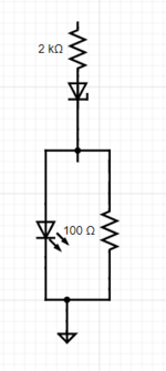
Take a look here,
TI_1.PNG


I have few more query,

1. My boss want me to put some common ground ZNR” Transient/Surge Absorbers, in folloing manner, https://www.farnell.com/datasheets/2244565.pdf

2. Dont think he needs it unnecessary for protection since there is 2 cap, 1 noise suppreser and rersistors are available.

3. He wants to add a fuse in pin 1 to R24, not sure why?

4 Can you imagine any idea to use R1-3? Those are 1 Mohms.

6. He wants to add a LED indecator for power output, for 5A current whats your idea?
 

Your schematic has R25 both ends see a ground icon. Is it intentional?

Re Q4...
Often it's recommended to include bleeder resistors in a power supply. After shut-off the purpose is to drain capacitors holding high voltage. Without bleeder resistors: (a) your power lamp may remain lit long after shut-off, (b) lethal shock remains to technician touching circuitry.
 
Last edited:
Your schematic has R25 both ends see a ground icon. Is it intentional?

Re Q4...
Often it's recommended to include bleeder resistors in a power supply. After shut-off the purpose is to drain capacitors holding high voltage. Without bleeder resistors: (a) your power lamp may remain lit long after shut-off, (b) lethal shock remains to technician touching circuitry.

R24-25 is just symbolic. You can assume a resistor like symbol.

Dont you mean bleeder resistor as discharging resistor for capacitor?

Let assume pin 2 and 3 are not connected
1. You did not talk about ZNR, does it meaningfull configuration.
2. Does L1 works with this datasheet? https://www.we-online.com/catalog/datasheet/74482210002.pdf.
3. Discharging resistor values are ok? Do you want me to see here, http://hyperphysics.phy-astr.gsu.edu/hbase/electric/capdis.html
Take a look the image below, my minimum required ripple current is 11.04 A. The output filter is a simple LC filter consisting of L2 and C7 in the typical circuit. We need to design the filter to have a cutoff frequency much lower than the operating frequency, so that it will effectively reduce the switching noise observed at the output.
OUT_1.PNG


Where the LED indicator should add?
 

Current sensor can be a low-ohm resistor, Hall effect sensor, etc.

Bargraph led's with window comparator:

electronic-projects.50webs.com/simple-led-voltmeter-circuit.htm

There is a simpler version using one op amp, with led's and resistors arranged like a ladder.
With a LED indicator on the output leads so one can see that the converter is likely putting out charging power. A 5K resistor in series with a LED would show if any voltage is present at the output (before it is connected to a battery). A 24-V 1W zener in series with a 2K resistor to the LED (with a 100-ohm in parallel with the LED) would show that the voltage is near the proper level, but either way the LED would not show if any current is flowing out to the batteries to be charged.
 

Attachments

  • led2.PNG
    led2.PNG
    7.9 KB · Views: 85

Place a low-ohm resistor in the current path. Measure voltage across it. Current through a resistor creates a proportionate voltage across it. Response is linear via Ohm's law.

Ohm value can be very low. Thus watt rating can be very low.

The op amp needs just a few mV to amplify it to a sensible reading. Feed its signal to bargraph led's (the 3914 IC is popular for driving 10 led's).

op amp measures voltage across current sensing resistor.jpeg
 
Regarding the questions about circuit protection...

With power source 250-650V, there is possibility of high voltage and arcing in the event a component in your circuit fails. There's a risk this high voltage can reach a lead-acid battery, creating a spark inside the compartment resulting in explosion, fire, etc. Or perhaps your battery is a different type with its own hazards you must give attention to.

In agreement with your boss, it's a good idea to install protective components. Perhaps your board has a device which is expensive or difficult to replace? That is the purpose of surge absorbers, MOV's, fuses, circuit breakers, etc.
Do you have any concerns about L1? How about its capacity?
Lets accept that ZNR and fuse should add.
--- Updated ---

Place a low-ohm resistor in the current path. Measure voltage across it. Current through a resistor creates a proportionate voltage across it. Response is linear via Ohm's law.

Ohm value can be very low. Thus watt rating can be very low.

The op amp needs just a few mV to amplify it to a sensible reading. Feed its signal to bargraph led's (the 3914 IC is popular for driving 10 led's).

View attachment 173483

3914 IC does not need external power?
 

3914 power supply can be 3-15V.

Here's a simple 5 led bargraph array suitable to indicate 1 to 5 Amperes. The screenshot shows the highest led just starting to light.
The triangle wave represents the volt level from your current sense circuit.

By putting 2 diodes between each stage, you get slightly better abrupt turn-on of each led. You can change it to 3 diodes although then the array needs a higher voltage to drive it.
Notice it needs 39 mA total, hence a plain op amp might not produce sufficient current to drive it.

bargraph 5 led's 0-7V (2 diode drops).png
 

Status
Not open for further replies.

Part and Inventory Search

Welcome to EDABoard.com

Sponsor

Back
Top