Continue to Site

Welcome to EDAboard.com

Welcome to our site! EDAboard.com is an international Electronics Discussion Forum focused on EDA software, circuits, schematics, books, theory, papers, asic, pld, 8051, DSP, Network, RF, Analog Design, PCB, Service Manuals... and a whole lot more! To participate you need to register. Registration is free. Click here to register now.

input protection circuit

Status
Not open for further replies.

lynch

Newbie level 6
Joined
Jul 3, 2007
Messages
11
Helped
0
Reputation
0
Reaction score
0
Trophy points
1,281
Activity points
1,371
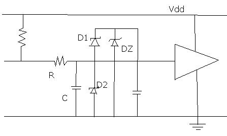
I currently have to design a analogue input circuit that measures 0-10v for an industrial envronment. The 0-10V will be buffered (op-amp) and then low pass filtered (RC) then used as a input to a ADC.

What circuits do people use to protect their inputs from over voltage, voltage spikes, shorts ...etc?

I mean apart from current limiting resistors how can i avoid damaging my op-amp input circuit.

I cannot find any useful literature on input protection circuitry and would appreciate a point in the right direction.

Many Thanks in advance for anyones help
 

generally SCRs are used for overvoltage protection and current diodes or other current limiting mechanisms are used for protection from excess current... keeping the glitches due to SCR in mind, diode are better in input protection compared to SCR...
 

Thanks Anand, but are there any usefull books on the subject with examples designs etc?
 

One of the most common input protection circuit consists of a resistor followed by 2 diodes: one connected between the ADC's input and +Vcc and one connected between the ADC's input and -Vdd (or 0V, if it is the lowest voltage in the circuit) ..
Here is an example:
**broken link removed**

Regards,
IanP
 

    lynch

    Points: 2
    Helpful Answer Positive Rating
89_1184259004.jpg


D1, D2 Shotky diodes
DZ Zener diode

If your input already have buffer, you dont have to use this from shematic...
This one I usualy use... It works just fine for me...
 

Adding a bit to Ianp's suggestion:

If the input goes above VCC + Vforward-diode, the diode between input to VCC gets forward biased and clamp the input. The diode to GND prevents input going below GND by more the Vforward.

Schottky diode is often used since they are fast acting and have lower Vf.

One drawback with this is your power supply now takes the ESD hit, so it might have to have a clamp circuit prevent the VCC from going up.
 

Thanks for the suggestion guys i will use these ideas and look around for some more material.

Question for the edge:
What wattage of zener diode do you use for your circut?

The pullup resistor before the RC is this a very high value? (100k)
 

Status
Not open for further replies.

Similar threads

Part and Inventory Search

Welcome to EDABoard.com

Sponsor

Back
Top