gustavolsilvano
Newbie level 4
Hello everybody,
I'm trying to simulate a dipole with a voltage source in the middle of them. For that, I'm using a lumped port that is found in the middle of the dipoles, and it have the voltage that I want. But i'm having a very small input impedance. An I doing something wrong?
I found to a model tutorial simulate that use the lumped port, that is the "rf coil", and it's found in the rf module paste.
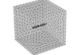
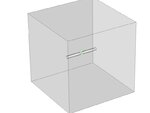
In the attachment is the geometry and where the lumped port is found, and my simulation too.
I'm using comsol 4.0a as my software.
Thanks

 View attachment Cópia de Teste1.rar
I'm trying to simulate a dipole with a voltage source in the middle of them. For that, I'm using a lumped port that is found in the middle of the dipoles, and it have the voltage that I want. But i'm having a very small input impedance. An I doing something wrong?
I found to a model tutorial simulate that use the lumped port, that is the "rf coil", and it's found in the rf module paste.
In the attachment is the geometry and where the lumped port is found, and my simulation too.
I'm using comsol 4.0a as my software.
Thanks

 View attachment Cópia de Teste1.rar
Last edited: