Continue to Site

Welcome to EDAboard.com

Welcome to our site! EDAboard.com is an international Electronics Discussion Forum focused on EDA software, circuits, schematics, books, theory, papers, asic, pld, 8051, DSP, Network, RF, Analog Design, PCB, Service Manuals... and a whole lot more! To participate you need to register. Registration is free. Click here to register now.

input impedance of RLC tank, and characteristic impedance

Status
Not open for further replies.

dxt78

Newbie level 4
Joined
Oct 5, 2007
Messages
6
Helped
0
Reputation
0
Reaction score
0
Trophy points
1,281
Activity points
1,324
Hello,
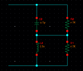
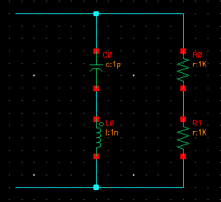
I have an RLC tank as shown in attachment (2R in parallel with an L and a C). I have two questions about it:
1) Why is the characteristic impedance of this LC tank sqrt(L/C) and what meaning does it have?
2) When computing the input resistance of this tank, what role should the characteristic impedance play?
Thanks.

84_1310658288.png
 

There is one single frequency wo=1/sqrt(LC) for which the reactive conductance of the capacitor
and of the inductor (wC and 1/wL), respectively, are equal.

Now the answer to your question:
If woC=1/woL you can insert the above expression for wo and you get:
woC=sqrt(C/L) and woL=sqrt(L/C).

In words: The characteristic impedance is the impedance of both reactive elements for w=wo (resonant frequency).
 
Last edited:

That means, at w=wo the conductance of the whole circuit is real and equals Y=1/R.
For the present circuit (ideal L and C), Y would be inifinite.
 
  • Like
Reactions: LvW

    LvW

    Points: 2
    Helpful Answer Positive Rating
I have corrected it already.
Thanks
LvW
 

LvW, thank you so much for your detailed reply. I suppose I was getting caught up in the definition of characteristic impedance as it pertains to transmission lines, but the math that you have described makes perfect sense. I am actually pursuing this problem as a way to calculate the input impedance of the circuit attached here:
45_1310661753.png


Using what you've described, I calculate Rin as 2R/[1+R/Z0], although...I have also seen it as 2R/[1+(R/Z0)^2]?? I must be making a mistake somewhere in the calculation.

---------- Post added at 18:36 ---------- Previous post was at 17:43 ----------

LvW, thank you so much for your detailed reply. I suppose I was getting caught up in the definition of characteristic impedance as it pertains to transmission lines, but the math that you have described makes perfect sense. I am actually pursuing this problem as a way to calculate the input impedance of the circuit attached here:
45_1310661753.png


Using what you've described, I calculate Rin as 2R/[1+R/Z0], although...I have also seen it as 2R/[1+(R/Z0)^2]?? I must be making a mistake somewhere in the calculation.

Actually the derivation described above is all wrong. If you account for the +j and -j for the inductor and capacitor impedances, you will get 2R/[1+(R/Z0)^2]
 

Status
Not open for further replies.

Part and Inventory Search

Welcome to EDABoard.com

Sponsor

Back
Top