Continue to Site

Welcome to EDAboard.com

Welcome to our site! EDAboard.com is an international Electronics Discussion Forum focused on EDA software, circuits, schematics, books, theory, papers, asic, pld, 8051, DSP, Network, RF, Analog Design, PCB, Service Manuals... and a whole lot more! To participate you need to register. Registration is free. Click here to register now.

Inphase & quadrature extraction

Status
Not open for further replies.

mordak

Member level 5
Member level 5
Joined
Mar 8, 2013
Messages
82
Helped
0
Reputation
0
Reaction score
0
Trophy points
1,286
Location
Neverland
Visit site
Activity points
2,134
Hi,

I have a question about extracting in-phase and quadrature (IQ) components of a signal. If we have an analog signal with frequency Fin, and want to use a system like the one in the attached picture, while Yk is the output of an ADC
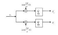


I was wondering whether there should be any relation between sampling frequency of the ADC and the input signal frequency in order to be able to extract IQ or not.

Thanks!
 

The answer depends on the intended modulation bandwidth and respective output filtering. In theory, keeping the Nyquiist criterion (Fin < Fs/2) allows to reproduce the input signal, means both quadrature components. But practically, you may want to sample Fin at least fourfold.
 

The answer depends on the intended modulation bandwidth and respective output filtering. In theory, keeping the Nyquiist criterion (Fin < Fs/2) allows to reproduce the input signal, means both quadrature components. But practically, you may want to sample Fin at least fourfold.

Thanks for your reply. I know about the nyquist rate, what I meant was any specific relation between sampling frequency of the ADC and input signal which is dictated by the IQ demodulator circuit. I was reading a paper, it was mentioned that when n is even, based on the orthogonality of triangle function we can derive I and Q as 0.5*A*cos(phi) and 0.5*A*sin(phi), where A and phi are amplitude and phase of the input signal, respectively.
I also performed a test like this in Matlab and could get good result, but when I inserted some offset to either input or sampling frequency (n would not be even and integer any more, say from 4 it would be changed to 3.999), the precision of the extracted amplitude and phase would be significantly degraded. I assume in the real world we cannot get two frequencies that precise with an integer and even ratio, so I am a bit confused, how come some papers report high resolution extracted voltage from their circuits?
 

If you are testing a theroretical statement, you need to care that your setup doesn't violate the premises of the theory. This might be the problem in your experiment.

You didn't show how you exactly measured the magnitude, particularly for a non-rational Fs:Fin ratio.
 
  • Like
Reactions: mordak

    mordak

    Points: 2
    Helpful Answer Positive Rating
If you are testing a theroretical statement, you need to care that your setup doesn't violate the premises of the theory. This might be the problem in your experiment.

You didn't show how you exactly measured the magnitude, particularly for a non-rational Fs:Fin ratio.

The way I perform the test is like this:
I apply an input sine signal with 1MHz to an ADC with say 15 bit resolution with sampling frequency of 4*1MHz+error. Then I will multiply the output of the ADC with two sine and cos of 1MHz. After multiplication I would have I and Q. Then I use I and Q in this formula (2/N)*sqrt(I^2+Q^2) to get the amplitude of the signal.
Then I will compare the extracted amplitude with my original input signal and based on that error I would define the SNR of the whole system. Is it the right approach to find the SNR of the whole system?
 

SNR should be determined in a spectral analyssis (FFT). Phase and magnitude errors in the measurement of the 1 MHz signal and DC offset won't be usually counted as noise.

As another point, you should apply a low-pass respectively a window when summing the samples, otherwise the discontinuity at the sequence ends will show up as apparent off-band component.
 

SNR should be determined in a spectral analyssis (FFT). Phase and magnitude errors in the measurement of the 1 MHz signal and DC offset won't be usually counted as noise.
.
There is one issue, the only thing that I care about is extracting amplitude and phase with 15 bit resolution. So basically I don't care about noise or other stuff (at least just in measurement), I just want to have a system which when I apply a voltage, the output of the system would be the extracted amplitude of the input with 15 bit resolution. So I thought (Hopefully I'm not wrong) I apply the input signal myself, so I know its amplitude, then I will find I and Q out of that system, so I can get the extracted amplitude.

Then I defined the resolution of the entire system in this way:
We know 1 LSB in an ADC is Vref/2^N (N is the resolution of the ADC), so if my extracted amplitude is supposed to have 15 bit resolution, the error between the actual amplitude and the extracted one should be less than 1LSB of a 15 bit ADC.
Resolution of the entire system would be log2 [ FS/ (Actual_amplitude - Extracted_amplitude) ] FS is the full scale of the system.
As another point, you should apply a low-pass respectively a window when summing the samples, otherwise the discontinuity at the sequence ends will show up as apparent off-band component.
.
I didn't get that, basically the accumulator in this system is a low pass, narrow band filter. So no extra filter is required. By the way, if you're talking about spectrum and using window to calculate the SNR, I'm finding the accuracy of the system in a different way, like I mentioned above.
 

basically the accumulator in this system is a low pass, narrow band filter
What's your exact integrator window? How many signal periods, rectangular or smooth window shape?
 

What's your exact integrator window? How many signal periods, rectangular or smooth window shape?

What I meant was this, I do not use any separate filter in this circuit. You just need to use a filter before ADC, after ADC every thing would be in digital domain. All this accumulation things would be done in DSP and with some registers, but now I am doing it in Matlab. Frankly I'm not sure about the math behind it, because after multiplier they would be both DC component and 2*Fin signal, but in those papers I have seen before, they don't use any separate filter after accumulator. Actually I'm still not sure how they can get rid of the 2*Fin product (after multiplier), but it seems they can! BTW, signal would be integrated over one cycle of the input signal.
 

BTW, signal would be integrated over one cycle of the input signal.
That's surely not a reasonable integration window when you have only 4 samples per cycle as stated in post #3. It will result in a large measurement uncertainty for non-rational frequency ratios.
 
  • Like
Reactions: mordak

    mordak

    Points: 2
    Helpful Answer Positive Rating
That's surely not a reasonable integration window when you have only 4 samples per cycle as stated in post #3. It will result in a large measurement uncertainty for non-rational frequency ratios.
What about the way I define the accuracy, like I said in my previous post, I look at the extracted voltage and then compare it to the input amplitude to find the resolution of the whole system, is it the right way? And is it necessary to use a filter after accumulator or not?
 

I'm sure there should be a filter, every signal analysis system has it to maximize SNR.

The accuracy can be determined by standard calibration methods. When defining the reference, a scale factor and time delay should be provided to take account of the ADC porperties.
 

The accuracy can be determined by standard calibration methods. When defining the reference, a scale factor and time delay should be provided to take account of the ADC porperties.

I didn't get what you said. Assume we consider everything about the ADC, and still output of the ADC has 15 bit resolution, how we can find whether the output of the demodulator being followed by the output of the ADC still has 15 bit resolution. (I mean getting SNR is the solution, or comapring the extracted amplitude with the actual one?)
I was thinking about getting SNR of the demodulator, but the problem is I need to choose a large number for FFT points, say 2^16. In normal operation, the demodulator would get 4, or 8 points per period, and needs to extract the amplitude based on those 4, or 8 points. But with choosing 2^16 points for FFT, now demodulator has more points, it means I will get better result. That's the reason I am not getting SNR of the output. Do you have any suggestion for that?
 

Apparently you have constraints for your design that haven't been explicitely stated. I said how I would operate the demodulator to get maximum performance.

SNR depends however on demodulation bandwidth. If you want to determine the measured quantity based on a single cycle without any filter, you get respective high noise. But if this is how your system is intended to operate, you should determine SNR with this setup.

You can transform the impulse response of your modulator to frequency domain and see if it fits your requirements.
 

Status
Not open for further replies.

Part and Inventory Search

Welcome to EDABoard.com

Sponsor

Back
Top