Infrared remote controllers are everywhere around us. The majority of home appliances are controlled using infrared remote controls. In this article/video, we learn to build a device that can decode (almost) any IR remote control and use the instructions to switch the relays (loads). So we can use this feature in a variety of applications without buying a new IR remote control and expensive hardware, such as turning ON/OFF the lights, opening/closing the curtains, ... etc. I have used an ATTiny85 microcontroller as the heart of the circuit. The device can record up to three IR codes in the EEPROM memory and switch 3 separate devices. Each relay can handle the currents up to 10A. The load switching mechanism (momentary ON/OFF, toggling, .. etc) can be programmed by the user.
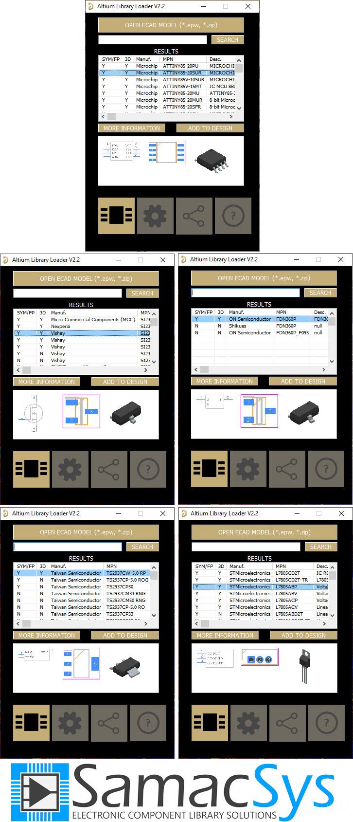
I used Altium Designer 21.4.1 and the SamacSys component libraries (SamacSys Altium Plugin) to design the Schematic and PCB. I also used the Siglent SDS2102X Plus/SDS1104X-E to analyze the IR signals.
The device works stable and reacts well to the transmitted IR signals. So let’s get started and build this puppy!

References
Original Article: **broken link removed**
[1]: Altium Designer electronic design CAD software: https://www.altium.com/altium-designer
[2]: SamacSys Altium plugin: https://www.samacsys.com/altium-designer-library-instructions
[3]: ATTiny85 schematic symbol, PCB footprint, 3D model: https://componentsearchengine.com/part-view/ATTINY85-20SUR/Microchip
[4]: TS2937-5.0 schematic symbol, PCB footprint, 3D model: https://componentsearchengine.com/part-view/TS2937CW-5.0 RP/Taiwan Semiconductor
[5]: L7805 schematic symbol, PCB footprint, 3D model: https://componentsearchengine.com/part-view/L7805CV/STMicroelectronics
[6]: SI2302 schematic symbol, PCB footprint, 3D model: https://componentsearchengine.com/part-view/SI2302DDS-T1-GE3/Vishay
[7]: FDN360P schematic symbol, PCB footprint, 3D model: https://componentsearchengine.com/part-view/FDN360P/ON Semiconductor
[8]: Siglent SDS2102X Plus oscilloscope: https://siglentna.com/products/digital-oscilloscope/sds2000xp-series-digital-phosphor-oscilloscope
[9]: Siglent SDS1104X-E oscilloscope: https://siglentna.com/digital-oscilloscopes/sds1000x-e-series-super-phosphor-oscilloscopes
I used Altium Designer 21.4.1 and the SamacSys component libraries (SamacSys Altium Plugin) to design the Schematic and PCB. I also used the Siglent SDS2102X Plus/SDS1104X-E to analyze the IR signals.
The device works stable and reacts well to the transmitted IR signals. So let’s get started and build this puppy!
References
Original Article: **broken link removed**
[1]: Altium Designer electronic design CAD software: https://www.altium.com/altium-designer
[2]: SamacSys Altium plugin: https://www.samacsys.com/altium-designer-library-instructions
[3]: ATTiny85 schematic symbol, PCB footprint, 3D model: https://componentsearchengine.com/part-view/ATTINY85-20SUR/Microchip
[4]: TS2937-5.0 schematic symbol, PCB footprint, 3D model: https://componentsearchengine.com/part-view/TS2937CW-5.0 RP/Taiwan Semiconductor
[5]: L7805 schematic symbol, PCB footprint, 3D model: https://componentsearchengine.com/part-view/L7805CV/STMicroelectronics
[6]: SI2302 schematic symbol, PCB footprint, 3D model: https://componentsearchengine.com/part-view/SI2302DDS-T1-GE3/Vishay
[7]: FDN360P schematic symbol, PCB footprint, 3D model: https://componentsearchengine.com/part-view/FDN360P/ON Semiconductor
[8]: Siglent SDS2102X Plus oscilloscope: https://siglentna.com/products/digital-oscilloscope/sds2000xp-series-digital-phosphor-oscilloscope
[9]: Siglent SDS1104X-E oscilloscope: https://siglentna.com/digital-oscilloscopes/sds1000x-e-series-super-phosphor-oscilloscopes

 ?
?