Continue to Site

Welcome to EDAboard.com

Welcome to our site! EDAboard.com is an international Electronics Discussion Forum focused on EDA software, circuits, schematics, books, theory, papers, asic, pld, 8051, DSP, Network, RF, Analog Design, PCB, Service Manuals... and a whole lot more! To participate you need to register. Registration is free. Click here to register now.

Industrial Multiple Voltage Switch Mode Power Supply Design.

Status
Not open for further replies.

tekati

Newbie level 1
Newbie level 1
Joined
May 24, 2014
Messages
1
Helped
0
Reputation
0
Reaction score
0
Trophy points
1
Visit site
Activity points
13
I am trying to build a multiple voltage switch mode power supply capable of harsh industrial environments. I have started the design but would like the assistance of seasoned designers to check my work, suggest changes and or tell me why it is a complete fail.

Schematic
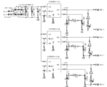
Power Supply Schematic.png

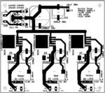
Board Layout
Power Supply Board.png
* * * NOTE: There is room between the pins and the body of the regulator even though it is not shown in the image. Also I noticed the net close to the body of the 12V regulator. That has already been addressed. * * *

Or if you would prefer the EagleCad files directly.
View attachment Power Supply.zip

I appreciate any constructive feedback.
 

Harsh industrial environment...this means a maximum operating temperature of...what? 0 to 60C, or -20 to 75C ?
You have to determine whether your heatsinking will be sufficient at worst case loading conditions, and apply the proper thermal solutions.

Also, what sort of IP rating will be required? I would guess IP67, which would prevent using fans.

Additionally, what other environmental concerns are required? Sulfur and harsh chemical tolerance? Conformal coating or even full potting may be required.

Vibration? Sturdy board support is required. Components may have to be RTV'd to the board, electrolytic caps for sure.

EMI and ESD? What ratings should it comply to? You may find that not only a significant amount of protection and suppressing devices are required, but the layout itself is very critical.

Failsafe operation? What can you do to prevent system damage is a component shorts out? Are you going to have monitoring and advise that a fault has occurred? Do you have a safety component of last resort, like a fuse? What if an output drops out of regulation or is overloaded, how do you communicate that? RS485, CANbus, a relay contact or at least a simple visual indicator?

What countries will this units be installed? Or to put it with other words, which regulatory agencies you must comply to?

What is the input voltage range? 12VAC is nominal, but what are the minimum and maximum ratings?

Does it have to be RoHS, or WEEE certified?

Any other specific requirements, like cycle-loss ride thru?
 

Another case of a "single post" member going AWOL, never to be heard of again.

In the future it may be better to ignore these posts.
 

Your simple buck regulators may be oscillating with insufficient load capacitance and low ESR for ripple or simply insufficient pre-load of 10% before the switch.

Please advise if adding preload helps on stability and larger low ESR Cout Caps.

- - - Updated - - -

Your simple buck regulators may be oscillating with insufficient load capacitance and low ESR for ripple or simply insufficient pre-load of 10% before the switch.

Please advise if adding preload helps on stability and larger low ESR Cout Caps. Increasing height size, and voltage to 16 V on polymer film caps will help greatly , such as Panasonic 330uF/16V.
 

Status
Not open for further replies.

Similar threads

Part and Inventory Search

Welcome to EDABoard.com

Sponsor

Back
Top