Continue to Site

Welcome to EDAboard.com

Welcome to our site! EDAboard.com is an international Electronics Discussion Forum focused on EDA software, circuits, schematics, books, theory, papers, asic, pld, 8051, DSP, Network, RF, Analog Design, PCB, Service Manuals... and a whole lot more! To participate you need to register. Registration is free. Click here to register now.

[SOLVED] Inductor with differential port in ADS

Status
Not open for further replies.

Hamid.Kiumarsi

Full Member level 2
Joined
Aug 18, 2010
Messages
142
Helped
33
Reputation
66
Reaction score
31
Trophy points
1,308
Location
Japan
Activity points
2,232
Dear all

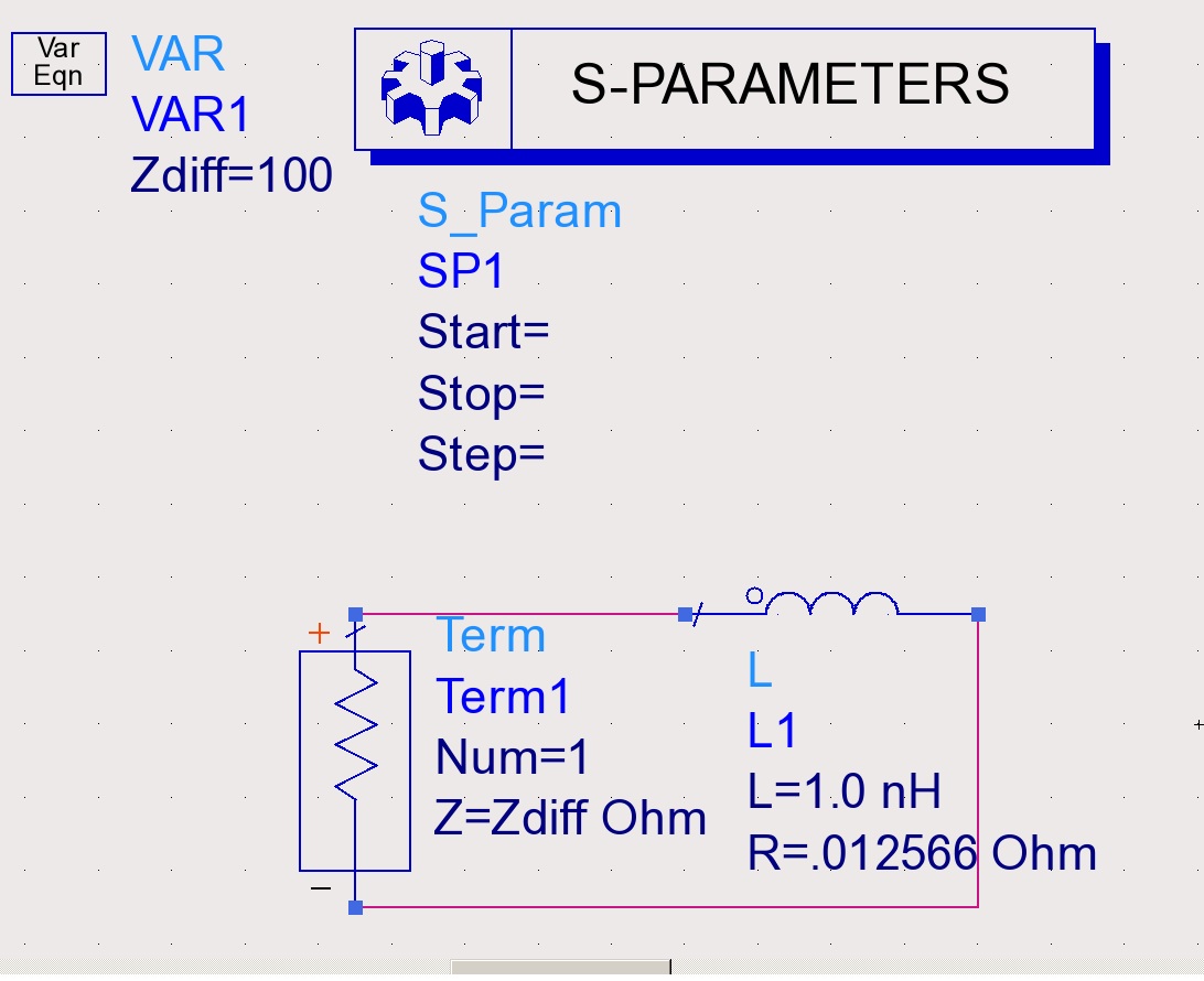
I have encountered a problem for simulating a very simple lumped inductor in ADS schematic.
The picture of schematic is attached.


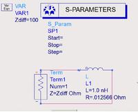
I am simulating this at 100 MHz, therefore with L=1nH, Q should be 50.
Using two single ports at the terminals of inductor is easy and gives the correct results. However when I am assigning differential port to the inductor S11 is something like -0.02dB.
It should be possible to get the correct result with differential port. I set the Zdiff of the port to 100 ohm and it didn't work either.

What am I doing wrong in my simulation?

waiting for your kind help
 

I don't know how your current setup can work, but **broken link removed**and here how you can use the ADS momentum to define each port type
 

Dear jackreloaded,

Thanks for reply. The links that you put in your post are for Momentum and actually I set up this simple schematic because I had this differential port problem in Momentum. Then I tried to understand that which part of my setting is wrong.

I drew an inductor and assigned a differential port to it in the same way as explained in the Momentum help document.
then I obtained s1p (one-port S parameters) for my inductor. S11 (dB) from Momentum results is -0.3dB! (I suppose that this should not be the S11 of my inductor)

Is this -0.3dB for differential port normal?
What pint am I missing in here?

---------- Post added at 13:36 ---------- Previous post was at 13:33 ----------

The correct value would be - 0.002dB
What value do you expect?

Thanks for reply,
Why the correct value is this?
Most probably I am confusing the single mode S parameters with mixed-mode ones.
Could you explain in detail that why S11 is not like -40dB?

By the way, Zdiff=100 ohm here is correct, right?
 

Could you explain in detail that why S11 is not like -40dB?

I see where your misunderstanding is.

For the two port case, your impedance into the circuit is 1nH + 0.012 Ohm + port impedance on the other side.
For the one port case, your impedance into the circuit is 1nH + 0.012 Ohm.

So for the one port case, you see approximately a short circuit and get S11 ~ 0dB. This is the correct result for a one port simulation, if the inductor has small value and small series resistance.
 

Dear volker_muehlhaus

Really thanks for your detailed explanation.

Now everything is clear.
Just one question: is Zdiff=100 ohm correct?
 

Just one question: is Zdiff=100 ohm correct?

The value is only relevant if you want to look at these S-parameters in the data display.

If you use the inductor results in the circuit, or calculate the L/Q values from the simulation results, the port impedance does not matter. You can use 50 ohm or 100 ohm, it makes no difference.
 

volker_muehlhaus

Dude thank you for explanation.

Regards,
Hamid
 

Status
Not open for further replies.

Part and Inventory Search

Welcome to EDABoard.com

Sponsor

Back
Top