David_
Advanced Member level 2
Hello.
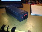
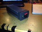
I have a real hard time getting to terms with the concept of inductor core saturation, I do get what saturation means and that it will make the inductance fall. But how to work out a cores max current is a mystery to me and that will be discussed in another thread but here I have made a circuit to measure the saturation current.
Its just a 12V power supply, capacitor bank, inductor under test followed by N-channel MOSFET who's gate is driven by a function generator.
a current sense resistor follows the MOSFET and this is the result:

I had hoped to see a slope which at some point starts to rise rapidly as the saturated core results in a faster rising current.
What am I doing wrong or am missing?
I have a real hard time getting to terms with the concept of inductor core saturation, I do get what saturation means and that it will make the inductance fall. But how to work out a cores max current is a mystery to me and that will be discussed in another thread but here I have made a circuit to measure the saturation current.
Its just a 12V power supply, capacitor bank, inductor under test followed by N-channel MOSFET who's gate is driven by a function generator.
a current sense resistor follows the MOSFET and this is the result:
I had hoped to see a slope which at some point starts to rise rapidly as the saturated core results in a faster rising current.
What am I doing wrong or am missing?


") )
)