Continue to Site

Welcome to EDAboard.com

Welcome to our site! EDAboard.com is an international Electronics Discussion Forum focused on EDA software, circuits, schematics, books, theory, papers, asic, pld, 8051, DSP, Network, RF, Analog Design, PCB, Service Manuals... and a whole lot more! To participate you need to register. Registration is free. Click here to register now.

Induction Problem in Microcontroller

Status
Not open for further replies.

rmrps

Member level 2
Member level 2
Joined
Oct 4, 2011
Messages
42
Helped
1
Reputation
2
Reaction score
1
Trophy points
1,288
Visit site
Activity points
1,635
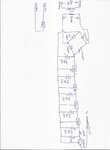
Hi Friends I am using Pic32mx460f512L controller my problem is when i switch off and on 230vac ceiling fan pic32 controller get disturbed and some times its get resetted i am tracing the power supply 24vac input via oscilloscope some unwanted hormonics coming from the 230v ac source when switch off and on 230vac fan i think i have to correct my power supply with best filter please give me your guidance to resolve this issue with best filter i have attached my power supply design please help to overcome induction problem Induction.jpg
 

there can be multiple reasons for this like layout, circuit etc., here are some thoughts:
1. All regulators are connected in cascade which is a bad power design. In this case, 7824 has to provide all the power for the board. U have to be sure if 7824 can provide handle that load i.e. current usage of board does not cross 1A max. Since, u r getting any issues during normal operating condition, i guess that problem is kind of sorted out. But still its bad design. Every regulator is better take input directly from rectifier output. This also makes 7824 generate lots of heat resulting in lots of power wastage or dissipation.

2. Linear regulators are less efficient and words on non switching technology, so the chance of power harmonics are less but not 0 due to power surges. Make sure, every section has separate space on board like power section, analog section digital section, filter section etc. This reduces interference due to coupling of circuit due to stray capacitance and inductance. Use decoupling and bypass caps ate every IC. A very usual cause is poorly decoupled circuit.

3. In layout, keep ground plane near MCU and behind MCU, to decouple any switching noise.

4. Switching on and off a motor i.e. fan takes sudden current due to increase in load, may discharge all caps on Vcc. Make sure power circuit is not loading. The brown out may be responsible for MCU to reset.

The exact answer requires complete layout and circuit. Since, it can be due to multiple reasons, i hope these suggestions may help.
Thanks
 

Hi,

I completely agree with ashugtiwari.

VCC decoupling, reset path decoupling, ground plane...

And all other signals. Every trace/wire acts like an antenna. The shorter the antenna the lower the induced voltage. ( and the lower the sent out power). Especially signals that leave the pcb. Here a filtering and/or protection diodes may improve stability.

Klaus
 
Hi there. Do you have 100nF ceramic caps CLOSE to the the uC power pins?
 

First of all I am little concerned why so many regulators used from 24V to 3.3V. Do you need all of those voltage points for your circuit powering? If not cut them down straight to the required voltage point.

The harmonics coupling to the microcontroller power line can be filtered out by using chokes and PI filers right after the AC-DC converter (after 1000uF). Also protection at microcontroller circuit as suggested in previous posts have to be considered.

Another option is use of STs device VIPER06 or similar.
https://www.st.com/web/en/resource/technical/document/datasheet/DM00048250.pdf
 

Status
Not open for further replies.

Similar threads

Part and Inventory Search

Welcome to EDABoard.com

Sponsor

Back
Top