Continue to Site

Welcome to EDAboard.com

Welcome to our site! EDAboard.com is an international Electronics Discussion Forum focused on EDA software, circuits, schematics, books, theory, papers, asic, pld, 8051, DSP, Network, RF, Analog Design, PCB, Service Manuals... and a whole lot more! To participate you need to register. Registration is free. Click here to register now.

Increasing max current of PWM output (Push-Pull?)

Status
Not open for further replies.

mwmerlo

Newbie level 4
Joined
Jun 22, 2010
Messages
6
Helped
0
Reputation
0
Reaction score
0
Trophy points
1,281
Activity points
1,323
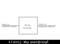
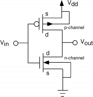
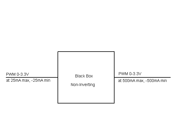
I would like to increase the maximum current that a PWM signal from a microcontroller can deliver from +-25mA to +-500mA. See image below. The output should have the same peak-to-peak voltage (0 to 3.3V) and should not be inverted (i.e. follows the input). I have looked into using an active push-pull output but the only configurations I can find is inverting (see image below). First, does anyone have suggestion on a digital push-pull circuit that will fit my needs? Also, is there a single chip solution to achieve this? I would prefer the circuit stay low cost and have a small footprint (for example sot-23).

Any help would be great.


81_1277570341.png

[/img]
 

What are you trying to accomplish? I'm by no means an expert, but I used PWM for controlling a simple heater output, and I simply connected V+ to the heater, then the low side of the heater to the drain of an NPN MOSFET, then the NPN mosfet source to ground.

+24V
|
|
|
R_heater
|
|
|
NPN
|
|
------ (GND)

I drove the mosfet w/my microcontroller, but it was running at a nominal 5V. That mosfet was designed for 5V operation, it's the Vishay SI4174DY and it's nothing short of awesome for a logic level mosfet. (https://mouser.com/ProductDetail/Vishay/SI4174DY-T1-GE3/?qs=cPOO8qjhL6OgQRlVVm1Qiw==)
 

does the output pwm signal is going to drive a mosfet ?

srizbf
26thjune2010
 

I am building a generic output much like a microcontroller output (push-pull) so I would like the output to be able to source and sink 500mA of current, not just sink as in dksoba's example.

@srizbf I am not specifically aiming to drive mosfets, why do you ask? Do you think a mosfet driver would work for me? I don't know much about them though so any information would be helpful.
 

such high currents are usually met with mosfet drivers.

srizbf
26thjune2010
 

The L293 is close. I need it to be powered by 3.3V and I only need one channel. Thanks for the suggestion. I'll keep looking.
 

I've got another solution for you: how about 2 transistors?
One example of a pair IRLML6402 and IRLML2502. They should cover you.
 

@bogdanc That does sound promising. How would you configure these two transistors?
 

As a buffer, just like in the schematic you gave.
 

But isn't that configuration inverting? Is there a way to configure it to be non-inverting? Or is an inverting buffer just a fact of life?
 

Oh, i am very sorry, I forgot about this requirement. One way is to use 2 inverters like this one after the other, with the first using smaller power transistor.
If you can have access to the software of the micro controller you could simply revert the PWM.
 

Perfect. It sounds like I will just have to use two inverting buffers. Thanks for the help.
 

Status
Not open for further replies.

Part and Inventory Search

Welcome to EDABoard.com

Sponsor

Back
Top