Continue to Site

Welcome to EDAboard.com

Welcome to our site! EDAboard.com is an international Electronics Discussion Forum focused on EDA software, circuits, schematics, books, theory, papers, asic, pld, 8051, DSP, Network, RF, Analog Design, PCB, Service Manuals... and a whole lot more! To participate you need to register. Registration is free. Click here to register now.

Incorrect connection of the wires on ATmega164

Status
Not open for further replies.

robi10101298

Junior Member level 2
Joined
May 7, 2020
Messages
20
Helped
0
Reputation
0
Reaction score
0
Trophy points
1
Activity points
117
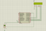
Hello guys,I'm trying to build a graphic display thermometer in Proteus, with an LM35 sensor using the ATmega 164 microcontroller.

My problem is that I don't know how to connect the temperature sensor to the microcontroller. When I'm trying to program this using the CodeVisionAVR I'm receving only errors, what can I do?

  • What am I doing wrong?
  • Are the wires connected OK? If not, why?

1606400487482.png
 

What am I doing wrong?
You don´t tell us which errors you get.

******
I don´t like simulations like this. Because they are far from reality.
* no AVR power supplies
* no AVR Ref voltage
* no AVR clock frequency
* no power supply capacitors
* no LPF/bypass signal capacitors
* no LCD power supply
* no LCD contrast voltage
* no code
* no timing information

Everything may cause a fail on real circuit. Some may even cause a fail on simulation.

* and maybe it´s a programmer/programming problem. Here we don´t have any infromation.

I´d say with the given informations it´s about impossible to help. ... just guess

Klaus
Right now I'm not interested in doing ,,the real thing", it's just for learning purposes.. I have made a code but I can't display the temperature on the display, I can only power it...Can you please help me?

C:
#include <mega164a.h>

#include <delay.h>

// Alphanumeric LCD functions
#include <alcd.h>

// Declare your global variables here

// Voltage Reference: 1.1V, cap. on AREF
#define ADC_VREF_TYPE ((1<<REFS1) | (0<<REFS0) | (1<<ADLAR))

// Read the 8 most significant bits
// of the AD conversion result
unsigned char read_adc(unsigned char adc_input)
{
ADMUX=adc_input | ADC_VREF_TYPE;
// Delay needed for the stabilization of the ADC input voltage
delay_us(10);
// Start the AD conversion
ADCSRA|=(1<<ADSC);
// Wait for the AD conversion to complete
while ((ADCSRA & (1<<ADIF))==0);
ADCSRA|=(1<<ADIF);
return ADCH;
}

void main(void)
{
LCD_Init();
       ADC_Init();
     
       LCD_Cmd(_LCD_CLEAR);
     
       LCD_Out(1,1,"Temperature");
// Declare your local variables here

// Crystal Oscillator division factor: 1
#pragma optsize-
CLKPR=(1<<CLKPCE);
CLKPR=(0<<CLKPCE) | (0<<CLKPS3) | (0<<CLKPS2) | (0<<CLKPS1) | (0<<CLKPS0);
#ifdef _OPTIMIZE_SIZE_
#pragma optsize+
#endif

// Input/Output Ports initialization
// Port A initialization
// Function: Bit7=In Bit6=In Bit5=In Bit4=In Bit3=In Bit2=In Bit1=In Bit0=In
DDRA=(0<<DDA7) | (0<<DDA6) | (0<<DDA5) | (0<<DDA4) | (0<<DDA3) | (0<<DDA2) | (0<<DDA1) | (0<<DDA0);
// State: Bit7=T Bit6=T Bit5=T Bit4=T Bit3=T Bit2=T Bit1=T Bit0=T
PORTA=(0<<PORTA7) | (0<<PORTA6) | (0<<PORTA5) | (0<<PORTA4) | (0<<PORTA3) | (0<<PORTA2) | (0<<PORTA1) | (0<<PORTA0);

// Port B initialization
// Function: Bit7=In Bit6=In Bit5=In Bit4=In Bit3=In Bit2=In Bit1=In Bit0=In
DDRB=(0<<DDB7) | (0<<DDB6) | (0<<DDB5) | (0<<DDB4) | (0<<DDB3) | (0<<DDB2) | (0<<DDB1) | (0<<DDB0);
// State: Bit7=T Bit6=T Bit5=T Bit4=T Bit3=T Bit2=T Bit1=T Bit0=T
PORTB=(0<<PORTB7) | (0<<PORTB6) | (0<<PORTB5) | (0<<PORTB4) | (0<<PORTB3) | (0<<PORTB2) | (0<<PORTB1) | (0<<PORTB0);

// Port C initialization
// Function: Bit7=In Bit6=In Bit5=In Bit4=In Bit3=In Bit2=In Bit1=In Bit0=In
DDRC=(0<<DDC7) | (0<<DDC6) | (0<<DDC5) | (0<<DDC4) | (0<<DDC3) | (0<<DDC2) | (0<<DDC1) | (0<<DDC0);
// State: Bit7=T Bit6=T Bit5=T Bit4=T Bit3=T Bit2=T Bit1=T Bit0=T
PORTC=(0<<PORTC7) | (0<<PORTC6) | (0<<PORTC5) | (0<<PORTC4) | (0<<PORTC3) | (0<<PORTC2) | (0<<PORTC1) | (0<<PORTC0);

// Port D initialization
// Function: Bit7=In Bit6=In Bit5=In Bit4=In Bit3=In Bit2=In Bit1=In Bit0=In
DDRD=(0<<DDD7) | (0<<DDD6) | (0<<DDD5) | (0<<DDD4) | (0<<DDD3) | (0<<DDD2) | (0<<DDD1) | (0<<DDD0);
// State: Bit7=T Bit6=T Bit5=T Bit4=T Bit3=T Bit2=T Bit1=T Bit0=T
PORTD=(0<<PORTD7) | (0<<PORTD6) | (0<<PORTD5) | (0<<PORTD4) | (0<<PORTD3) | (0<<PORTD2) | (0<<PORTD1) | (0<<PORTD0);

// Timer/Counter 0 initialization
// Clock source: System Clock
// Clock value: Timer 0 Stopped
// Mode: Normal top=0xFF
// OC0A output: Disconnected
// OC0B output: Disconnected
TCCR0A=(0<<COM0A1) | (0<<COM0A0) | (0<<COM0B1) | (0<<COM0B0) | (0<<WGM01) | (0<<WGM00);
TCCR0B=(0<<WGM02) | (0<<CS02) | (0<<CS01) | (0<<CS00);
TCNT0=0x00;
OCR0A=0x00;
OCR0B=0x00;

// Timer/Counter 1 initialization
// Clock source: System Clock
// Clock value: Timer1 Stopped
// Mode: Normal top=0xFFFF
// OC1A output: Disconnected
// OC1B output: Disconnected
// Noise Canceler: Off
// Input Capture on Falling Edge
// Timer1 Overflow Interrupt: Off
// Input Capture Interrupt: Off
// Compare A Match Interrupt: Off
// Compare B Match Interrupt: Off
TCCR1A=(0<<COM1A1) | (0<<COM1A0) | (0<<COM1B1) | (0<<COM1B0) | (0<<WGM11) | (0<<WGM10);
TCCR1B=(0<<ICNC1) | (0<<ICES1) | (0<<WGM13) | (0<<WGM12) | (0<<CS12) | (0<<CS11) | (0<<CS10);
TCNT1H=0x00;
TCNT1L=0x00;
ICR1H=0x00;
ICR1L=0x00;
OCR1AH=0x00;
OCR1AL=0x00;
OCR1BH=0x00;
OCR1BL=0x00;

// Timer/Counter 2 initialization
// Clock source: System Clock
// Clock value: Timer2 Stopped
// Mode: Normal top=0xFF
// OC2A output: Disconnected
// OC2B output: Disconnected
ASSR=(0<<EXCLK) | (0<<AS2);
TCCR2A=(0<<COM2A1) | (0<<COM2A0) | (0<<COM2B1) | (0<<COM2B0) | (0<<WGM21) | (0<<WGM20);
TCCR2B=(0<<WGM22) | (0<<CS22) | (0<<CS21) | (0<<CS20);
TCNT2=0x00;
OCR2A=0x00;
OCR2B=0x00;

// Timer/Counter 0 Interrupt(s) initialization
TIMSK0=(0<<OCIE0B) | (0<<OCIE0A) | (0<<TOIE0);

// Timer/Counter 1 Interrupt(s) initialization
TIMSK1=(0<<ICIE1) | (0<<OCIE1B) | (0<<OCIE1A) | (0<<TOIE1);

// Timer/Counter 2 Interrupt(s) initialization
TIMSK2=(0<<OCIE2B) | (0<<OCIE2A) | (0<<TOIE2);

// External Interrupt(s) initialization
// INT0: Off
// INT1: Off
// INT2: Off
// Interrupt on any change on pins PCINT0-7: Off
// Interrupt on any change on pins PCINT8-15: Off
// Interrupt on any change on pins PCINT16-23: Off
// Interrupt on any change on pins PCINT24-31: Off
EICRA=(0<<ISC21) | (0<<ISC20) | (0<<ISC11) | (0<<ISC10) | (0<<ISC01) | (0<<ISC00);
EIMSK=(0<<INT2) | (0<<INT1) | (0<<INT0);
PCICR=(0<<PCIE3) | (0<<PCIE2) | (0<<PCIE1) | (0<<PCIE0);

// USART0 initialization
// USART0 disabled
UCSR0B=(0<<RXCIE0) | (0<<TXCIE0) | (0<<UDRIE0) | (0<<RXEN0) | (0<<TXEN0) | (0<<UCSZ02) | (0<<RXB80) | (0<<TXB80);

// USART1 initialization
// USART1 disabled
UCSR1B=(0<<RXCIE1) | (0<<TXCIE1) | (0<<UDRIE1) | (0<<RXEN1) | (0<<TXEN1) | (0<<UCSZ12) | (0<<RXB81) | (0<<TXB81);

// Analog Comparator initialization
// Analog Comparator: Off
// The Analog Comparator's positive input is
// connected to the AIN0 pin
// The Analog Comparator's negative input is
// connected to the AIN1 pin
ACSR=(1<<ACD) | (0<<ACBG) | (0<<ACO) | (0<<ACI) | (0<<ACIE) | (0<<ACIC) | (0<<ACIS1) | (0<<ACIS0);
// Digital input buffer on AIN0: On
// Digital input buffer on AIN1: On
DIDR1=(0<<AIN0D) | (0<<AIN1D);

// ADC initialization
// ADC Clock frequency: 1000.000 kHz
// ADC Voltage Reference: 1.1V, cap. on AREF
// ADC Auto Trigger Source: Free Running
// Only the 8 most significant bits of
// the AD conversion result are used
// Digital input buffers on ADC0: On, ADC1: On, ADC2: On, ADC3: On
// ADC4: On, ADC5: On, ADC6: On, ADC7: On
DIDR0=(0<<ADC7D) | (0<<ADC6D) | (0<<ADC5D) | (0<<ADC4D) | (0<<ADC3D) | (0<<ADC2D) | (0<<ADC1D) | (0<<ADC0D);
ADMUX=ADC_VREF_TYPE;
ADCSRA=(1<<ADEN) | (0<<ADSC) | (1<<ADATE) | (0<<ADIF) | (0<<ADIE) | (0<<ADPS2) | (1<<ADPS1) | (1<<ADPS0);
ADCSRB=(0<<ADTS2) | (0<<ADTS1) | (0<<ADTS0);

// SPI initialization
// SPI disabled
SPCR=(0<<SPIE) | (0<<SPE) | (0<<DORD) | (0<<MSTR) | (0<<CPOL) | (0<<CPHA) | (0<<SPR1) | (0<<SPR0);

// TWI initialization
// TWI disabled
TWCR=(0<<TWEA) | (0<<TWSTA) | (0<<TWSTO) | (0<<TWEN) | (0<<TWIE);

// Alphanumeric LCD initialization
// Connections are specified in the
// Project|Configure|C Compiler|Libraries|Alphanumeric LCD menu:
// RS - PORTC Bit 0
// RD - PORTB Bit 1
// EN - PORTC Bit 1
// D4 - PORTC Bit 2
// D5 - PORTC Bit 3
// D6 - PORTC Bit 4
// D7 - PORTC Bit 5
// Characters/line: 20
lcd_init(20);

    //declare pins for LCD
sbit LCD_RS at PORTC0_bit;
sbit LCD_EN at PORTC1_bit;
sbit LCD_D4 at PORTC2_bit;
sbit LCD_D5 at PORTC3_bit;
sbit LCD_D6 at PORTC4_bit;
sbit LCD_D7 at PORTC5_bit;

sbit LCD_RS_Direction at DDC0_bit;
sbit LCD_EN_Direction at DDC1_bit;
sbit LCD_D4_Direction at DDC2_bit;
sbit LCD_D5_Direction at DDC3_bit;
sbit LCD_D6_Direction at DDC4_bit;
sbit LCD_D7_Direction at DDC5_bit;
           char arr[11]="0123456789";
while (1)
      {
      // Place your code here
            int res = 0;
          res=ADC_Read(0);
          LCD_Chr(2,1,arr[res/100%10]);
          LCD_Chr(2,2,arr[res/10%10]);
          LCD_Chr(2,3,arr[res%10]);
      }
}
 
Last edited:

Hi,

did you read my post?
* about error description --> If you don´t post an error description, helping will be difficult
* about power supply --> If you don´t connect a power supply, the microcontroller won´t work
* it´s not sufficient that there is a code line "// Voltage Reference: 1.1V, cap. on AREF#" ... while there is no cap on AREF in real circuit.
* ...

Maybe the posted schematic does not match the real circuit --> then post a valid schematic (how else can we know how your circuit looks like)

Klaus
I don't have any error displayed since the program that I have here compiles successfully, but as I've said I can only power the display and that's it..The power supply it's connected from the pin nr 4(Reset)
 

This is what I have now: My problem is that I can't translate mikroC code to CodeVisionAVR language :( How can I translate this to CodeVision Code:
C:
char arr[11]="0123456789";

int res = 0;

res=ADC_Read(0);

          LCD_Chr(2,1,arr[res/100%10]);

          LCD_Chr(2,2,arr[res/10%10]);       

          LCD_Chr(2,3,arr[res%10]);


This is the final code:
C:
#include <mega164a.h>

#include <delay.h>

// Alphanumeric LCD functions
#include <alcd.h>
 #include <stdio.h> 
 #include "defs.h"
// Declare your global variables here
  
// Voltage Reference: 1.1V, cap. on AREF
#define ADC_VREF_TYPE ((1<<REFS1) | (0<<REFS0) | (1<<ADLAR))

// Read the 8 most significant bits
// of the AD conversion result
unsigned char read_adc(unsigned char adc_input)
{
ADMUX=adc_input | ADC_VREF_TYPE;
// Delay needed for the stabilization of the ADC input voltage
delay_us(10);
// Start the AD conversion
ADCSRA|=(1<<ADSC);
// Wait for the AD conversion to complete
while ((ADCSRA & (1<<ADIF))==0);
ADCSRA|=(1<<ADIF);
return ADCH;
}

void main(void)
{
// Declare your local variables here
// Crystal Oscillator division factor: 1
#pragma optsize-
CLKPR=(1<<CLKPCE);
CLKPR=(0<<CLKPCE) | (0<<CLKPS3) | (0<<CLKPS2) | (0<<CLKPS1) | (0<<CLKPS0);
#ifdef _OPTIMIZE_SIZE_
#pragma optsize+
#endif

// Input/Output Ports initialization
// Port A initialization
// Function: Bit7=In Bit6=In Bit5=In Bit4=In Bit3=In Bit2=In Bit1=In Bit0=In
DDRA=(0<<DDA7) | (0<<DDA6) | (0<<DDA5) | (0<<DDA4) | (0<<DDA3) | (0<<DDA2) | (0<<DDA1) | (0<<DDA0);
// State: Bit7=T Bit6=T Bit5=T Bit4=T Bit3=T Bit2=T Bit1=T Bit0=T
PORTA=(0<<PORTA7) | (0<<PORTA6) | (0<<PORTA5) | (0<<PORTA4) | (0<<PORTA3) | (0<<PORTA2) | (0<<PORTA1) | (0<<PORTA0);

// Port B initialization
// Function: Bit7=In Bit6=In Bit5=In Bit4=In Bit3=In Bit2=In Bit1=In Bit0=In
DDRB=(0<<DDB7) | (0<<DDB6) | (0<<DDB5) | (0<<DDB4) | (0<<DDB3) | (0<<DDB2) | (0<<DDB1) | (0<<DDB0);
// State: Bit7=T Bit6=T Bit5=T Bit4=T Bit3=T Bit2=T Bit1=T Bit0=T
PORTB=(0<<PORTB7) | (0<<PORTB6) | (0<<PORTB5) | (0<<PORTB4) | (0<<PORTB3) | (0<<PORTB2) | (0<<PORTB1) | (0<<PORTB0);

// Port C initialization
// Function: Bit7=In Bit6=In Bit5=In Bit4=In Bit3=In Bit2=In Bit1=In Bit0=In
DDRC=(0<<DDC7) | (0<<DDC6) | (0<<DDC5) | (0<<DDC4) | (0<<DDC3) | (0<<DDC2) | (0<<DDC1) | (0<<DDC0);
// State: Bit7=T Bit6=T Bit5=T Bit4=T Bit3=T Bit2=T Bit1=T Bit0=T
PORTC=(0<<PORTC7) | (0<<PORTC6) | (0<<PORTC5) | (0<<PORTC4) | (0<<PORTC3) | (0<<PORTC2) | (0<<PORTC1) | (0<<PORTC0);

// Port D initialization
// Function: Bit7=In Bit6=In Bit5=In Bit4=In Bit3=In Bit2=In Bit1=In Bit0=In
DDRD=(0<<DDD7) | (0<<DDD6) | (0<<DDD5) | (0<<DDD4) | (0<<DDD3) | (0<<DDD2) | (0<<DDD1) | (0<<DDD0);
// State: Bit7=T Bit6=T Bit5=T Bit4=T Bit3=T Bit2=T Bit1=T Bit0=T
PORTD=(0<<PORTD7) | (0<<PORTD6) | (0<<PORTD5) | (0<<PORTD4) | (0<<PORTD3) | (0<<PORTD2) | (0<<PORTD1) | (0<<PORTD0);

// Timer/Counter 0 initialization
// Clock source: System Clock
// Clock value: Timer 0 Stopped
// Mode: Normal top=0xFF
// OC0A output: Disconnected
// OC0B output: Disconnected
TCCR0A=(0<<COM0A1) | (0<<COM0A0) | (0<<COM0B1) | (0<<COM0B0) | (0<<WGM01) | (0<<WGM00);
TCCR0B=(0<<WGM02) | (0<<CS02) | (0<<CS01) | (0<<CS00);
TCNT0=0x00;
OCR0A=0x00;
OCR0B=0x00;

// Timer/Counter 1 initialization
// Clock source: System Clock
// Clock value: Timer1 Stopped
// Mode: Normal top=0xFFFF
// OC1A output: Disconnected
// OC1B output: Disconnected
// Noise Canceler: Off
// Input Capture on Falling Edge
// Timer1 Overflow Interrupt: Off
// Input Capture Interrupt: Off
// Compare A Match Interrupt: Off
// Compare B Match Interrupt: Off
TCCR1A=(0<<COM1A1) | (0<<COM1A0) | (0<<COM1B1) | (0<<COM1B0) | (0<<WGM11) | (0<<WGM10);
TCCR1B=(0<<ICNC1) | (0<<ICES1) | (0<<WGM13) | (0<<WGM12) | (0<<CS12) | (0<<CS11) | (0<<CS10);
TCNT1H=0x00;
TCNT1L=0x00;
ICR1H=0x00;
ICR1L=0x00;
OCR1AH=0x00;
OCR1AL=0x00;
OCR1BH=0x00;
OCR1BL=0x00;

// Timer/Counter 2 initialization
// Clock source: System Clock
// Clock value: Timer2 Stopped
// Mode: Normal top=0xFF
// OC2A output: Disconnected
// OC2B output: Disconnected
ASSR=(0<<EXCLK) | (0<<AS2);
TCCR2A=(0<<COM2A1) | (0<<COM2A0) | (0<<COM2B1) | (0<<COM2B0) | (0<<WGM21) | (0<<WGM20);
TCCR2B=(0<<WGM22) | (0<<CS22) | (0<<CS21) | (0<<CS20);
TCNT2=0x00;
OCR2A=0x00;
OCR2B=0x00;

// Timer/Counter 0 Interrupt(s) initialization
TIMSK0=(0<<OCIE0B) | (0<<OCIE0A) | (0<<TOIE0);

// Timer/Counter 1 Interrupt(s) initialization
TIMSK1=(0<<ICIE1) | (0<<OCIE1B) | (0<<OCIE1A) | (0<<TOIE1);

// Timer/Counter 2 Interrupt(s) initialization
TIMSK2=(0<<OCIE2B) | (0<<OCIE2A) | (0<<TOIE2);

// External Interrupt(s) initialization
// INT0: Off
// INT1: Off
// INT2: Off
// Interrupt on any change on pins PCINT0-7: Off
// Interrupt on any change on pins PCINT8-15: Off
// Interrupt on any change on pins PCINT16-23: Off
// Interrupt on any change on pins PCINT24-31: Off
EICRA=(0<<ISC21) | (0<<ISC20) | (0<<ISC11) | (0<<ISC10) | (0<<ISC01) | (0<<ISC00);
EIMSK=(0<<INT2) | (0<<INT1) | (0<<INT0);
PCICR=(0<<PCIE3) | (0<<PCIE2) | (0<<PCIE1) | (0<<PCIE0);

// USART0 initialization
// USART0 disabled
UCSR0B=(0<<RXCIE0) | (0<<TXCIE0) | (0<<UDRIE0) | (0<<RXEN0) | (0<<TXEN0) | (0<<UCSZ02) | (0<<RXB80) | (0<<TXB80);

// USART1 initialization
// USART1 disabled
UCSR1B=(0<<RXCIE1) | (0<<TXCIE1) | (0<<UDRIE1) | (0<<RXEN1) | (0<<TXEN1) | (0<<UCSZ12) | (0<<RXB81) | (0<<TXB81);

// Analog Comparator initialization
// Analog Comparator: Off
// The Analog Comparator's positive input is
// connected to the AIN0 pin
// The Analog Comparator's negative input is
// connected to the AIN1 pin
ACSR=(1<<ACD) | (0<<ACBG) | (0<<ACO) | (0<<ACI) | (0<<ACIE) | (0<<ACIC) | (0<<ACIS1) | (0<<ACIS0);
// Digital input buffer on AIN0: On
// Digital input buffer on AIN1: On
DIDR1=(0<<AIN0D) | (0<<AIN1D);

// ADC initialization
// ADC Clock frequency: 625.000 kHz
// ADC Voltage Reference: 1.1V, cap. on AREF
// ADC Auto Trigger Source: Free Running
// Only the 8 most significant bits of
// the AD conversion result are used
// Digital input buffers on ADC0: On, ADC1: On, ADC2: On, ADC3: On
// ADC4: On, ADC5: On, ADC6: On, ADC7: On
DIDR0=(0<<ADC7D) | (0<<ADC6D) | (0<<ADC5D) | (0<<ADC4D) | (0<<ADC3D) | (0<<ADC2D) | (0<<ADC1D) | (0<<ADC0D);
ADMUX=ADC_VREF_TYPE;
ADCSRA=(1<<ADEN) | (0<<ADSC) | (1<<ADATE) | (0<<ADIF) | (0<<ADIE) | (1<<ADPS2) | (0<<ADPS1) | (1<<ADPS0);
ADCSRB=(0<<ADTS2) | (0<<ADTS1) | (0<<ADTS0);

// SPI initialization
// SPI disabled
SPCR=(0<<SPIE) | (0<<SPE) | (0<<DORD) | (0<<MSTR) | (0<<CPOL) | (0<<CPHA) | (0<<SPR1) | (0<<SPR0);

// TWI initialization
// TWI disabled
TWCR=(0<<TWEA) | (0<<TWSTA) | (0<<TWSTO) | (0<<TWEN) | (0<<TWIE);

// Alphanumeric LCD initialization
// Connections are specified in the
// Project|Configure|C Compiler|Libraries|Alphanumeric LCD menu:
// RS - PORTC Bit 0
// RD - PORTC Bit 1
// EN - PORTC Bit 2
// D4 - PORTC Bit 4
// D5 - PORTC Bit 5
// D6 - PORTC Bit 6
// D7 - PORTC Bit 7
// Characters/line: 20
lcd_init(20);
//char arr[11]="0123456789";
lcd_gotoxy(0,0);
// display the message
lcd_putsf("Temp is:");
lcd_gotoxy(0,1);
lcd_putsf("? 13 A3 ");
printf("\r\nSwVersion:%d.%d\r\n", SW_VERSION/10, SW_VERSION%10);

while (1)
      {
      // Place your code here
      }
}
 

Hi,

post#5: " I don't have any error displayed "
post#1: "I'm receving only errors "

???

Klaus
 

Hi,

post#5: " I don't have any error displayed "
post#1: "I'm receving only errors "

???

Klaus
Sorry, I've edited the code meanwhile but it's not working as expected..
 

but it's not working as expected
Another useless information, because nobody knows what you expect and what you see instead.

You randomly jump from a wiring issue to a programming issue to a compiling issue to a language issue..... I can´t follow this.

I´m out. You need someone else who has more patience.
Good luck.

Klaus
 

Another useless information, because nobody knows what you expect and what you see instead.

You randomly jump from a wiring issue to a programming issue to a compiling issue to a language issue..... I can´t follow this.

I´m out. You need someone else who has more patience.
Good luck.

Klaus
Sorry Klaus, I'm a beginner in this area, I just want to pass my subject and I don't know what to do, I have a teacher that doesn't want to help us so I need to figure out myself how can I solve this problem... What I need to do is to build a graphic display thermometer in Proteus, with an LM35 sensor using the ATmega 164 microcontroller. My problem is that I've successfully turned on the LCD Display, but it's not taking the temperature from the sensor because I don't know how to do this using the CodeVisionAVR compiler...
 

Hi,

O.K. one last try:

You need to:
* focus on one item. One!
* provide complete information for this item.
* answer questions.
* give useful feedback on the given recommendations.
* give feedback when an item is soved.
* give feedback when you move to another item.

My recommendation: Start with the real circuit. Photos, complete schematic, additional informations, clear detailed question.

Klaus
Unfortunately I don't have the access to some real components...I couldn't find on the internet a complete schematic for ATmega164 and LM35 sensor, so that's why it's a little bit complicated for me to do it...
--- Updated ---

To rewrite my question:

So, what I want to achieve in this is project is to build a circuit that can measure the temperature using an LM35 sensor from the ATmega164 board. I'll draw this circuit using the Proteus and I'll write the code using the CodeVisionAVR. What I've achieved until now it's that I can successfully display a text on the LCD. I've attached to you how my schematic it's looking:
1606418661039.png


And this is the code:

C:
/*******************************************************
This program was created by the CodeWizardAVR V3.42
Automatic Program Generator
© Copyright 1998-2020 Pavel Haiduc, HP InfoTech S.R.L.
http://www.hpinfotech.ro

Project :
Version :
Date    : 26-Nov-2020
Author  :
Company :
Comments:


Chip type               : ATmega164PA
Program type            : Application
AVR Core Clock frequency: 20.000000 MHz
Memory model            : Small
External RAM size       : 0
Data Stack size         : 256
*******************************************************/

#include <mega164a.h>

#include <delay.h>

// Alphanumeric LCD functions
#include <alcd.h>

// Declare your global variables here

// Voltage Reference: 1.1V, cap. on AREF
#define ADC_VREF_TYPE ((1<<REFS1) | (0<<REFS0) | (1<<ADLAR))

// Read the 8 most significant bits
// of the AD conversion result
unsigned char read_adc(unsigned char adc_input)
{
ADMUX=adc_input | ADC_VREF_TYPE;
// Delay needed for the stabilization of the ADC input voltage
delay_us(10);
// Start the AD conversion
ADCSRA|=(1<<ADSC);
// Wait for the AD conversion to complete
while ((ADCSRA & (1<<ADIF))==0);
ADCSRA|=(1<<ADIF);
return ADCH;
}

void main(void)
{
// Declare your local variables here

// Crystal Oscillator division factor: 1
#pragma optsize-
CLKPR=(1<<CLKPCE);
CLKPR=(0<<CLKPCE) | (0<<CLKPS3) | (0<<CLKPS2) | (0<<CLKPS1) | (0<<CLKPS0);
#ifdef _OPTIMIZE_SIZE_
#pragma optsize+
#endif

// Input/Output Ports initialization
// Port A initialization
// Function: Bit7=In Bit6=In Bit5=In Bit4=In Bit3=In Bit2=In Bit1=In Bit0=In
DDRA=(0<<DDA7) | (0<<DDA6) | (0<<DDA5) | (0<<DDA4) | (0<<DDA3) | (0<<DDA2) | (0<<DDA1) | (0<<DDA0);
// State: Bit7=T Bit6=T Bit5=T Bit4=T Bit3=T Bit2=T Bit1=T Bit0=T
PORTA=(0<<PORTA7) | (0<<PORTA6) | (0<<PORTA5) | (0<<PORTA4) | (0<<PORTA3) | (0<<PORTA2) | (0<<PORTA1) | (0<<PORTA0);

// Port B initialization
// Function: Bit7=In Bit6=In Bit5=In Bit4=In Bit3=In Bit2=In Bit1=In Bit0=In
DDRB=(0<<DDB7) | (0<<DDB6) | (0<<DDB5) | (0<<DDB4) | (0<<DDB3) | (0<<DDB2) | (0<<DDB1) | (0<<DDB0);
// State: Bit7=T Bit6=T Bit5=T Bit4=T Bit3=T Bit2=T Bit1=T Bit0=T
PORTB=(0<<PORTB7) | (0<<PORTB6) | (0<<PORTB5) | (0<<PORTB4) | (0<<PORTB3) | (0<<PORTB2) | (0<<PORTB1) | (0<<PORTB0);

// Port C initialization
// Function: Bit7=In Bit6=In Bit5=In Bit4=In Bit3=In Bit2=In Bit1=In Bit0=In
DDRC=(0<<DDC7) | (0<<DDC6) | (0<<DDC5) | (0<<DDC4) | (0<<DDC3) | (0<<DDC2) | (0<<DDC1) | (0<<DDC0);
// State: Bit7=T Bit6=T Bit5=T Bit4=T Bit3=T Bit2=T Bit1=T Bit0=T
PORTC=(0<<PORTC7) | (0<<PORTC6) | (0<<PORTC5) | (0<<PORTC4) | (0<<PORTC3) | (0<<PORTC2) | (0<<PORTC1) | (0<<PORTC0);

// Port D initialization
// Function: Bit7=In Bit6=In Bit5=In Bit4=In Bit3=In Bit2=In Bit1=In Bit0=In
DDRD=(0<<DDD7) | (0<<DDD6) | (0<<DDD5) | (0<<DDD4) | (0<<DDD3) | (0<<DDD2) | (0<<DDD1) | (0<<DDD0);
// State: Bit7=T Bit6=T Bit5=T Bit4=T Bit3=T Bit2=T Bit1=T Bit0=T
PORTD=(0<<PORTD7) | (0<<PORTD6) | (0<<PORTD5) | (0<<PORTD4) | (0<<PORTD3) | (0<<PORTD2) | (0<<PORTD1) | (0<<PORTD0);

// Timer/Counter 0 initialization
// Clock source: System Clock
// Clock value: Timer 0 Stopped
// Mode: Normal top=0xFF
// OC0A output: Disconnected
// OC0B output: Disconnected
TCCR0A=(0<<COM0A1) | (0<<COM0A0) | (0<<COM0B1) | (0<<COM0B0) | (0<<WGM01) | (0<<WGM00);
TCCR0B=(0<<WGM02) | (0<<CS02) | (0<<CS01) | (0<<CS00);
TCNT0=0x00;
OCR0A=0x00;
OCR0B=0x00;

// Timer/Counter 1 initialization
// Clock source: System Clock
// Clock value: Timer1 Stopped
// Mode: Normal top=0xFFFF
// OC1A output: Disconnected
// OC1B output: Disconnected
// Noise Canceler: Off
// Input Capture on Falling Edge
// Timer1 Overflow Interrupt: Off
// Input Capture Interrupt: Off
// Compare A Match Interrupt: Off
// Compare B Match Interrupt: Off
TCCR1A=(0<<COM1A1) | (0<<COM1A0) | (0<<COM1B1) | (0<<COM1B0) | (0<<WGM11) | (0<<WGM10);
TCCR1B=(0<<ICNC1) | (0<<ICES1) | (0<<WGM13) | (0<<WGM12) | (0<<CS12) | (0<<CS11) | (0<<CS10);
TCNT1H=0x00;
TCNT1L=0x00;
ICR1H=0x00;
ICR1L=0x00;
OCR1AH=0x00;
OCR1AL=0x00;
OCR1BH=0x00;
OCR1BL=0x00;

// Timer/Counter 2 initialization
// Clock source: System Clock
// Clock value: Timer2 Stopped
// Mode: Normal top=0xFF
// OC2A output: Disconnected
// OC2B output: Disconnected
ASSR=(0<<EXCLK) | (0<<AS2);
TCCR2A=(0<<COM2A1) | (0<<COM2A0) | (0<<COM2B1) | (0<<COM2B0) | (0<<WGM21) | (0<<WGM20);
TCCR2B=(0<<WGM22) | (0<<CS22) | (0<<CS21) | (0<<CS20);
TCNT2=0x00;
OCR2A=0x00;
OCR2B=0x00;

// Timer/Counter 0 Interrupt(s) initialization
TIMSK0=(0<<OCIE0B) | (0<<OCIE0A) | (0<<TOIE0);

// Timer/Counter 1 Interrupt(s) initialization
TIMSK1=(0<<ICIE1) | (0<<OCIE1B) | (0<<OCIE1A) | (0<<TOIE1);

// Timer/Counter 2 Interrupt(s) initialization
TIMSK2=(0<<OCIE2B) | (0<<OCIE2A) | (0<<TOIE2);

// External Interrupt(s) initialization
// INT0: Off
// INT1: Off
// INT2: Off
// Interrupt on any change on pins PCINT0-7: Off
// Interrupt on any change on pins PCINT8-15: Off
// Interrupt on any change on pins PCINT16-23: Off
// Interrupt on any change on pins PCINT24-31: Off
EICRA=(0<<ISC21) | (0<<ISC20) | (0<<ISC11) | (0<<ISC10) | (0<<ISC01) | (0<<ISC00);
EIMSK=(0<<INT2) | (0<<INT1) | (0<<INT0);
PCICR=(0<<PCIE3) | (0<<PCIE2) | (0<<PCIE1) | (0<<PCIE0);

// USART0 initialization
// USART0 disabled
UCSR0B=(0<<RXCIE0) | (0<<TXCIE0) | (0<<UDRIE0) | (0<<RXEN0) | (0<<TXEN0) | (0<<UCSZ02) | (0<<RXB80) | (0<<TXB80);

// USART1 initialization
// USART1 disabled
UCSR1B=(0<<RXCIE1) | (0<<TXCIE1) | (0<<UDRIE1) | (0<<RXEN1) | (0<<TXEN1) | (0<<UCSZ12) | (0<<RXB81) | (0<<TXB81);

// Analog Comparator initialization
// Analog Comparator: Off
// The Analog Comparator's positive input is
// connected to the AIN0 pin
// The Analog Comparator's negative input is
// connected to the AIN1 pin
ACSR=(1<<ACD) | (0<<ACBG) | (0<<ACO) | (0<<ACI) | (0<<ACIE) | (0<<ACIC) | (0<<ACIS1) | (0<<ACIS0);
// Digital input buffer on AIN0: On
// Digital input buffer on AIN1: On
DIDR1=(0<<AIN0D) | (0<<AIN1D);

// ADC initialization
// ADC Clock frequency: 625.000 kHz
// ADC Voltage Reference: 1.1V, cap. on AREF
// ADC Auto Trigger Source: Free Running
// Only the 8 most significant bits of
// the AD conversion result are used
// Digital input buffers on ADC0: On, ADC1: On, ADC2: On, ADC3: On
// ADC4: On, ADC5: On, ADC6: On, ADC7: On
DIDR0=(0<<ADC7D) | (0<<ADC6D) | (0<<ADC5D) | (0<<ADC4D) | (0<<ADC3D) | (0<<ADC2D) | (0<<ADC1D) | (0<<ADC0D);
ADMUX=ADC_VREF_TYPE;
ADCSRA=(1<<ADEN) | (0<<ADSC) | (1<<ADATE) | (0<<ADIF) | (0<<ADIE) | (1<<ADPS2) | (0<<ADPS1) | (1<<ADPS0);
ADCSRB=(0<<ADTS2) | (0<<ADTS1) | (0<<ADTS0);

// SPI initialization
// SPI disabled
SPCR=(0<<SPIE) | (0<<SPE) | (0<<DORD) | (0<<MSTR) | (0<<CPOL) | (0<<CPHA) | (0<<SPR1) | (0<<SPR0);

// TWI initialization
// TWI disabled
TWCR=(0<<TWEA) | (0<<TWSTA) | (0<<TWSTO) | (0<<TWEN) | (0<<TWIE);

// Alphanumeric LCD initialization
// Connections are specified in the
// Project|Configure|C Compiler|Libraries|Alphanumeric LCD menu:
// RS - PORTC Bit 0
// RD - PORTC Bit 1
// EN - PORTC Bit 2
// D4 - PORTC Bit 4
// D5 - PORTC Bit 5
// D6 - PORTC Bit 6
// D7 - PORTC Bit 7
// Characters/line: 20
lcd_init(20);
     lcd_gotoxy(0,0);
    // display the message
    lcd_putsf("Temp is:");
    lcd_gotoxy(0,1);
    lcd_putsf("? 13 13 ");
    //printf("\r\nSwVersion:%d.%d\r\n", SW_VERSION/10, SW_VERSION%10);
while (1)
      {
      // Place your code here

      }
}
 

Attachments

  • 1606418563466.png
    1606418563466.png
    164 KB · Views: 63
Last edited:

Assuming that the simulated dispaly is showing the text you show in the diagram
i.e
Temp is:
? 13 A3
then the program is doing alost exactly what you are telling it to do. I would have expected the second line to be
? 13 13, so there is somethiing to be fixed there as to why is the first 13 OK and not the second, when your code is printing
? 13 13 to the LCD.
The reason you are not getting anything else is that it doesn't look like you are not telling it to do anything after lcd_putsf("? 13 13 ");
The program is just sitting in a while loop.
The comment // Place your code here in the template is there for a good reason.
If there is no code, unless you have set up timer interrupts to do the work nothing will happen.
I'm not familliar with the ATMEGA and don't have the inclination to work through the set up code to see what interrupts you have set up.
I can't see any code outside the two statements in the main function that writes to the LCD. At first look it seems you need to write some code in the while (1) loop to read the ADC convert the binary value to degrees C then dispaly the result.
 

Status
Not open for further replies.

Similar threads

Part and Inventory Search

Welcome to EDABoard.com

Sponsor

Back
Top