Continue to Site

Welcome to EDAboard.com

Welcome to our site! EDAboard.com is an international Electronics Discussion Forum focused on EDA software, circuits, schematics, books, theory, papers, asic, pld, 8051, DSP, Network, RF, Analog Design, PCB, Service Manuals... and a whole lot more! To participate you need to register. Registration is free. Click here to register now.

INA219 reading problem

Status
Not open for further replies.

johnny78

Full Member level 4
Joined
Jun 28, 2017
Messages
209
Helped
1
Reputation
2
Reaction score
4
Trophy points
18
Activity points
1,723
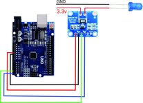
i have INA219 module for my Project But i have some problem with it

i have tested the getcurrent example supplied with the library

i have connected a led from the arduino 3.3v terminal for testing the but the reading is not steady
i get readings between 6.70 ma - 7.20

is it ok ? to get this vary
any ideas please
Code:
#include <Wire.h>
#include <Adafruit_INA219.h>

Adafruit_INA219 ina219;


void setup(void)
{
  Serial.begin(115200);
  while (!Serial) {
      // will pause Zero, Leonardo, etc until serial console opens
      delay(1);
  }

  uint32_t currentFrequency;
    
  Serial.println("Hello!");
 
  // Initialize the INA219.
  // By default the initialization will use the largest range (32V, 2A).  However
  // you can call a setCalibration function to change this range (see comments).
  if (! ina219.begin()) {
    Serial.println("Failed to find INA219 chip");
    while (1) { delay(10); }
  }
  // To use a slightly lower 32V, 1A range (higher precision on amps):
  //ina219.setCalibration_32V_1A();
  // Or to use a lower 16V, 400mA range (higher precision on volts and amps):
  //ina219.setCalibration_16V_400mA();

  Serial.println("Measuring voltage and current with INA219 ...");
}

void loop(void)
{
  float shuntvoltage = 0;
  float busvoltage = 0;
  float current_mA = 0;
  float loadvoltage = 0;
  float power_mW = 0;

  shuntvoltage = ina219.getShuntVoltage_mV();
  busvoltage = ina219.getBusVoltage_V();
  current_mA = ina219.getCurrent_mA();
  power_mW = ina219.getPower_mW();
  loadvoltage = busvoltage + (shuntvoltage / 1000);
 
  Serial.print("Bus Voltage:   "); Serial.print(busvoltage); Serial.println(" V");
  Serial.print("Shunt Voltage: "); Serial.print(shuntvoltage); Serial.println(" mV");
  Serial.print("Load Voltage:  "); Serial.print(loadvoltage); Serial.println(" V");
  Serial.print("Current:       "); Serial.print(current_mA); Serial.println(" mA");
  Serial.print("Power:         "); Serial.print(power_mW); Serial.println(" mW");
  Serial.println("");

  delay(2000);
}
 

Hi,

first thigs first:
* which INA module exactly?
* which Arduino module exactly?
* wiring schematic of all your circuit.
* what power supply do you use?
* which library exactly?
* show the terminal software outputs.

Klaus
 

Hello!

Beside this, you should also specify what you are measuring.
-> you measure, you check the electrical characteristics in INA219 documentation,
and you should be able to conclude by yourself whether the differences you are measuring
are within the bounds specified in the datasheet.

Dora.
 

the differencs are between 0.10 - 0.50ma
Hello!

Beside this, you should also specify what you are measuring.
-> you measure, you check the electrical characteristics in INA219 documentation,
and you should be able to conclude by yourself whether the differences you are measuring
are within the bounds specified in the datasheet.

Dora.
--- Updated ---

Hi,

first thigs first:
* which INA module exactly?
* which Arduino module exactly?
* wiring schematic of all your circuit.
* what power supply do you use?
* which library exactly?
* show the terminal software outputs.

Klaus
INA219 Current sensor with arduino UNO with adafruit ina219 library
im reading the results on Serial monitor & i get between 0.10 - 0.50 difference almost on each reading

im terting on leds So one of then give me 4ma at rading & the other 7ma
is tht ok?
 

Attachments

  • wiringIna219.jpg
    wiringIna219.jpg
    80 KB · Views: 387

Hi,

your picture:
* Arduino UNO shows SDA ans SCL at right top header pins. Why don´t you use them?
* LEDs usually need a current limiting resistor. I miss it.
* Why did you swap Vin- and Vin+ at the sensor PCB? (But it should work this way, too)

Klaus
 

Hi,

your picture:
* Arduino UNO shows SDA ans SCL at right top header pins. Why don´t you use them?
* LEDs usually need a current limiting resistor. I miss it.
* Why did you swap Vin- and Vin+ at the sensor PCB? (But it should work this way, too)

Klaus
i've used 470 ohm resistor for the led & i've connected the Vin correctly
so do u think almost 0.50mA max difference is ok ?
 

Hello!

Difficult to guess what the system does, and I don't feel like reading the
datasheet for you.
However, there is a 100 shunt resistor. If the chip is powered in 5V and if
this 5V serves as a reference for the ADC, it means that you can measure at most
5V across the 100 ohms resistor, therefore 50 mA crossing the resistor.
Now if you look at the errors in the datasheet, there are many of them, but
all of them within 1%. 1% of 50 mA is 0.5 mA.
Then it also depends on the stability of your power source, etc.
So, do your homework, read the documentation and try to get your own conclusions.
First, try to validate the "ifs" above.

Dora.
 

    johnny78

    Points: 2
    Helpful Answer Positive Rating
Hi,
I don't feel like reading the
datasheet for you.
Me too.

And please do some simple math using Ohm´s law.
We will correct you if there is any mistake or misunderstanding.

***
I see the shunt as 100mOhms.
R100 means 0R100 or 0.1R .... not 100R

***

You don´t take much effort, like answering all the questions and posting datasheet links..

But I had a quick view on IN219 datasheet.
I can imagine how they come to a 400mA range (=0.04V/0.1 Ohms)
But don´t know why they come to 1A or 2A.

I guess it´s in the module datasheet or library documentation. .. I don´t have by hand...

Klaus
 

    johnny78

    Points: 2
    Helpful Answer Positive Rating
Hello!

I see the shunt as 100mOhms.

Right. And it makes more sense for a shunt. Sorry.
That said, I didn't notice the 400 mA range, but anyway having a
fluctuation of 0.5 mA for a 400 mA range is not bad.

Dora.
 

    johnny78

    Points: 2
    Helpful Answer Positive Rating
thanks Guys

im testing on the 3.3v of the Arduino Uno for the VCC it must be steady i guess
So 0.5mA for few mA's is a big loose
maybe because of the wires im testing with ?
i will try the connection on a Pcb
the positive Volt for testing is regulated with lm317 & the negative is passing throught IRFZ46 mosfet
is there anything wrong with this ?
 

Hi,

Some basic things you have to think about / read / calculate.

* What´s the current measurement range?
* What´s the voltage across the shunt with 0.5mA?

Klaus
 

Hello!


Right. And it makes more sense for a shunt. Sorry.
That said, I didn't notice the 400 mA range, but anyway having a
fluctuation of 0.5 mA for a 400 mA range is not bad.

Dora.
hello Guys
im working on the project now & yes without any load the reading is between 0.1 - 0.5ma
i have selected the 16v 400mA mode
& with 1A 12v Lamp im reading 375mA with the 400mA mode(Just for testing)
i guess its a good result.
the maximum current i need is 300mA i think no more

in the get current example they use 2 seconds delay between readings
im trying to find this in the datasheet but i cant find it
so is it necessary ?


thanks
 
Last edited:

Hi
& with 1A 12v Lamp im reading 375mA with the 400mA mode(Just for testing)
i guess its a good result.
Why do you guess? I think you have all the information .. we don´t. We just have the information you give.

I can´t see why a 375mA result is good for a 1A lamp...

in the get current example they use 2 seconds delay between readings
Usually the datasheet tells
* data rate
* conversion time
* sampling rate
or something similar

Klaus
 

Hi

Why do you guess? I think you have all the information .. we don´t. We just have the information you give.

I can´t see why a 375mA result is good for a 1A lamp...


Usually the datasheet tells
* data rate
* conversion time
* sampling rate
or something similar

Klaus
the lamp is not 1A i've used a dvm & the reading is almost the same
& im sensing it on 5v or 6.3v not 12 & i mean its good because i have used the 400mA mode so i thought its the max current it can measure

thanks Klaus i will check the datasheet again
 

Status
Not open for further replies.

Similar threads

Part and Inventory Search

Welcome to EDABoard.com

Sponsor

Back
Top