Continue to Site

Welcome to EDAboard.com

Welcome to our site! EDAboard.com is an international Electronics Discussion Forum focused on EDA software, circuits, schematics, books, theory, papers, asic, pld, 8051, DSP, Network, RF, Analog Design, PCB, Service Manuals... and a whole lot more! To participate you need to register. Registration is free. Click here to register now.

Improving Current limit

Status
Not open for further replies.

jonnybgood

Full Member level 4
Joined
Dec 28, 2010
Messages
214
Helped
3
Reputation
6
Reaction score
1
Trophy points
1,298
Activity points
3,011
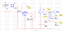
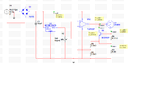
I built the attached power supply which in simulation gave very good results. When I built the circuit on a veroboard without the current limiting stage I also had very good regulation.

When I added the current limiting part I noticed that it didn't work as good as the simulation I had a range of about 250mA. I am testing my power supply with 10Ω 5Watts, 3.3Ω % watts and 1Ω % Watts. My current limit is at 2.7Amps.

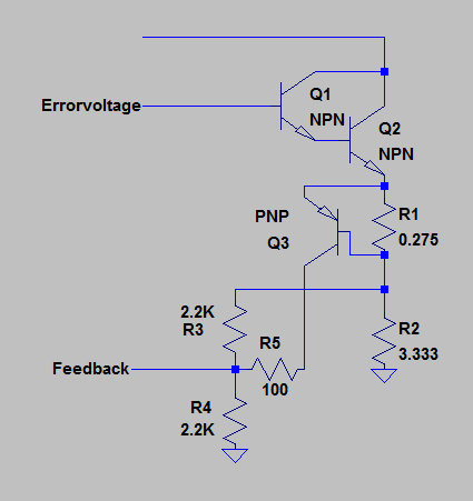
Therefore I am using the 3.3Ω resistor to set my current limit to 2.7Amps which should leave a 9V across it. I am very careful with regards to ground as I am always measuring voltage with my probe connected to the lead of the rectifier. With the current sense resistor of 0.275Ω as in the schematic, the current limit already kicks in to drop the voltage to 8.6V. On the other hand when I play around different resistances to obtain nearly the 9V back, the current limit with 1Ω load would climb to 2.9Amps.

Is there a way I can improve my current limit maybe a transistor with a different gain. I tried BC549 and BC547 and the two gave me poor results. BDW my darlington is TIP122.
 

Attachments

  • psu.png
    psu.png
    33.9 KB · Views: 129
  • limiting.png
    limiting.png
    37 KB · Views: 107

In that schematic, Q2 will deliver current not just to the feedback network, but also to the load, meaning that it will have to conduct a lot of current (most of which goes to the load, which you don't want) to start limiting current. Try the circuit below:
100_1327412665.png

This way the current limit transistor diverts current away from the load and directly towards the feedback voltage. The value of R5 can be adjusted to change the "sensitivity" of the current limit.
 
Hello my friend!
You circuit has many problems .
i can describe some of them for you:
1st: this type of current limiter is not optimum . you should move it to ground ( to obtain better regulation.)
2nd: your series pass transistor : you should connect a series resistor with it's base and then a resistor from it's collector to base.
And when your current wants to become limited your out put voltage should decrease automatically but not very high . ( at short circuit your out voltage will be about zero ).
BTW , would you like to have variable current limiter? if yes , i can help you to design that.
Good luck
 
In that schematic, Q2 will deliver current not just to the feedback network, but also to the load, meaning that it will have to conduct a lot of current (most of which goes to the load, which you don't want) to start limiting current. Try the circuit below:
100_1327412665.png

This way the current limit transistor diverts current away from the load and directly towards the feedback voltage. The value of R5 can be adjusted to change the "sensitivity" of the current limit.

I tried your configuration with a 100Ω but with 3.3Ω my voltage came down to 7.2V (worse). Then I tried with 820Ω and I couldn't see a lot of difference. :s Do you have any idea what i might be doing wrong?

---------- Post added at 16:51 ---------- Previous post was at 16:45 ----------

Can you suggest some resistor values to start with? when you suggested to move the current limit to ground what do you mean exactly please? I do not need variable current but if I can set it to a particular value forever thats fine for me.
 
Last edited:

I got this idea from these notes where the current sense resistor was calculated with a lot of formulas.
 

Attachments

  • equation.pptx.png
    equation.pptx.png
    431.3 KB · Views: 131

Dear friend ,your Q3 is driving the emitter current pulling away from the main path.The 100onhm or 1000ohm in series have no effect owing to high collector impedance.The feedback shall be stable at 50% of the voltage drop across 3.33ohm....what have you achieved ?It might be better to trim the R4 to give a change in feedback voltages for current limiting .
 

Then I would have to change the op amp ... because I am already using the TL072 on a single supply and I do not think it would be a good idea deacrease the inverting input dow to 0.3V
 

I tried your configuration with a 100Ω but with 3.3Ω my voltage came down to 7.2V (worse). Then I tried with 820Ω and I couldn't see a lot of difference. :s Do you have any idea what i might be doing wrong?
That's actually what you should expect. The limit transistor only needs to be slightly on to work, so it probably only needs Vbe=0.6. So your current limit will be 0.6/0.275=2.18A, and your Vout should be 2.18*3.33=7.27V. So the value of the current limit has decreased, but it should be much more stable and independent of the load. To adjust the current limit, just change the sense resistor.
Can you suggest some resistor values to start with? when you suggested to move the current limit to ground what do you mean exactly please? I do not need variable current but if I can set it to a particular value forever thats fine for me.
The value of R5 really just changes the "sharpness" of the transition from constant voltage to constant current. It's not really critical, and just needs to be lower than the impedance of the feedback divider.

Also you should be aware that both your circuit and mine will only limit current to a certain degree. It will only lower the output voltage down to around the reference voltage given to the error amplifier. So these circuits won't work for short-circuit conditions. To work a short circuit, you will need a slightly more complex design.
 

Dear Friend
Again Hi
Use below circuit to obtain good current limiting and variable current limit ( as i know , the tl072 has 2 op amp , one of them can be used for current limit ):
Supply.JPG
R6 is load resistor . and by changing the v3 ( it is equal to the vR7) you can control your current simply . ( to select your desired current) .
Best Wishes
Goldsmith
 
  • Like
Reactions: rbk17c

    rbk17c

    Points: 2
    Helpful Answer Positive Rating
Dear Friend
Again Hi
Use below circuit to obtain good current limiting and variable current limit ( as i know , the tl072 has 2 op amp , one of them can be used for current limit ):
View attachment 67918
R6 is load resistor . and by changing the v3 ( it is equal to the vR7) you can control your current simply . ( to select your desired current) .
Best Wishes
Goldsmith

thanks a lot for your time. I simulated it with multisim and got very good results and I plan to build it tomorrow. I need to ask you some questions if you dont mind:

What is the advantage of cascading the darlington with another NPN transistor?
I see you put the reference divider from Q2 emitter to ground, how does this work just the same as connecting it only accross load like mine?

What are the purpose of the filters exaclty in this circuit?

thanks again

Brandon
 

Dear Brandon
Hi
The purpose of c1 : increasing the ripple rejection ratio ( at dc it considered open circuit , and at ripply , it will be short circuit (approx) ) thus the feed back network can sense the ripple faster than constant DC voltage.
And C2 : the current that will flow from R2 , is not stable and it will have large value of ripple . with that capacitor , i prevented from interference between the ripple and constant DC and thus the voltage of base will be very constant .
If you use darlington pair , the out put impedance of your power supply will decrease and it's out put current will increase ( it's ability to give current) BTW you can use 2 transistor ( 2n3055 in parallel with together to obtain lower dissipation).
( and if you want use parallel transistors , you should use a 0.1 or 0.27 ohms resistor in series with their emitters ( each transistor , one resistor ) To provide , the balanced pair.
Good luck
Goldsmith
 

I guess you noticed, that using an OP error amplifier for the constant current path promises a more exact current regulation than the simple Vbe based current limiter form your initial post. Looking at the schematic in post #9 demands a comment that dynamic behaviour of both current and voltage regulation, as well as the transition between both modes should be also checked thoroughly. I have a doubt that it may be not so good in this case.
 

    mstfozkan

    Points: 2
    Helpful Answer Positive Rating
Dear Brandon
Hi
The purpose of c1 : increasing the ripple rejection ratio ( at dc it considered open circuit , and at ripply , it will be short circuit (approx) ) thus the feed back network can sense the ripple faster than constant DC voltage.
And C2 : the current that will flow from R2 , is not stable and it will have large value of ripple . with that capacitor , i prevented from interference between the ripple and constant DC and thus the voltage of base will be very constant .
If you use darlington pair , the out put impedance of your power supply will decrease and it's out put current will increase ( it's ability to give current) BTW you can use 2 transistor ( 2n3055 in parallel with together to obtain lower dissipation).
( and if you want use parallel transistors , you should use a 0.1 or 0.27 ohms resistor in series with their emitters ( each transistor , one resistor ) To provide , the balanced pair.
Good luck
Goldsmith

Can you think of a tweak in the biasing of the PNP transistor in the current limiting stage as my limiting is not linear. To set current limit at 2.7A at 1Ω Ohm load I will then have a 0.5V drop at 10Ω load.
 

Dear FvM
Hi
As i tested that circuit that i have designed it , it's procedure was , terrific . and without any problem.
Best Regards
Goldsmith
 

Dear FvM
Hi
As i tested that circuit that i have designed it , it's procedure was , terrific . and without any problem.
Best Regards
Goldsmith

How can I check the output of the op amp at the current limiting stage pls? I changes the op amp to an LM358N to be safe.
 

What do you want to measure accurately? its out put? you should measure , that with oscilloscope.
Respect
 

I changes the op amp to an LM358N to be safe.
Good point, I didn't notice the problem yet. In fact the original circuit doesn't work without a dual OP supply, or current measurement shunts with at least 3 V voltage drop.

What I meant with dynamic behaviour is the response to load steps or varying setpoints, if intended at all. But if your specification doesn't require these things, the circuit may be O.K.

A realistic scenario to consider is a lab supply, powering a circuit that will require to strictly keep a supply voltage limit. You short the supply unintentionally, than release the short. What happens with the supply voltage? Will it keep safe limits or raise above acceptable linits during the transient response?
 

Build the circuit many factors came out. Like voltage drop on secondary transformer output. This caused the voltage to drop than actually rise on the current sense resistor when the a resistor of 1.5 Ohms is put as a dummy load. The transformer I am using is from a car battery charger rated at 4Amps. I dont think I have control over this issue. I have a bigger transformer 12v output but it is very heavy. Is it the last option I have for this circuit to work or can I use another current limiting method?
 

Dear jonnybgood
Again Hi
As i told you , we have many many different way for current controlling . but this way is usual and very good , and when the out put voltage is short circuit , the voltage can not increase ( remember that this circuit called hiccup current limiter , and at one time the current limiter , do it's duty , and at the other time , the voltage feed back will do it's duty .
BTW : i built 25A power supply with this way about 2 years ago.
Best Wishes
Goldsmith
 

Status
Not open for further replies.

Similar threads

Part and Inventory Search

Welcome to EDABoard.com

Sponsor

Back
Top